Archive for September, 2008

Circuit Bending

Tuesday, September 30th, 2008

Have you ever taken apart a kid’s electronic toy to see how it worked? Maybe tried to cut the wires or rewire the circuitboard? That’s how circuit benders begin their hobby.

Circuit bending is the creative, short-circuiting of electronic devices such as low voltage, battery-powered guitar effects, children’s toys and small digital synthesizers to create new musical or visual instruments and sound generators.

One of the most popular toys to circuit bend is the “Speak n Spell”. Here’s a great demonstration of circuit bending featuring a Speak n Spell:

Resistors In Series

Tuesday, September 30th, 2008

Electronic components used in electronic circuits to regulate and limit the flow of electric current in the circuit are known as Resistors. Resistors can be connected in two basic configurations – in series and in parallel.

When connected in a series connection, the resistors are connected in a line. The current flows through the resistors one after the other.

When the resistors are connected in such a configuration, they exhibit the following properties:

The current flowing through each of the resistors is the same, that is, I total = I1 + I2 + I3…and so on. This is due to the fact that there is only one path for the current to flow through. The second property that they exhibit is that the total voltage drop across all the resistors connected in series is equal to the sum of the individual voltages of the resistors, that is, V total = V1 + V2 + V3…

Now since, V = IR, so, V total = I R equiv, which comes down to,
I R equiv = I1.R1 + I2.R2 + …, and since I1 = I2 = I3 .., we have
I. R equiv = I. (R1 + R2 + R3..), or R equiv = R1 + R2 + R3..

So the equivalent resistance of these electronic components connected in series is the sum of the individual resistances.

Resistors in series are often used for obtaining specific higher resistance values which are otherwise not available. They are also used in voltage divider circuits. A common application is in household wiring.

Early Crystal Radios

Saturday, September 27th, 2008

Requiring no battery, the crystal radio was one of the earliest forms of radio having been developed in the late 1800s and early 1900s. At this time the crystal radio sets were used to receive Morse code messages, but as time progressed the voice messages could also be received by such sets. This progression had much to do with an improvement in materials, which included the diodes and tuning coil. Even with an improvement in materials though, the construction of a radio set was fairly simple to achieve.

By the 1920s and 1930s radio was taking off, but the sets were expensive objects to buy and so the crystal radio was the cheap alternative that could be built at home. Most major newspapers would run guides on how to build such radios, and it was information that was put to good use during the Second World War. During the war, allied Prisoners of War made use of the materials that they had on hand, to build their own radios, to find out news of the fighting. The soldiers would use recovered wire for the tuning coil and antenna, and make diodes from everyday material, like the pencil lead.

The crystal radio is still used by many people around the world today, although now it is usually a hobby rather than a necessity. In most cases, radio sets are now fairly cheap and mass produced making the building of a crystal radio a pleasure rather than something that needs to be done.

The Basics of Potentiometers

Monday, September 22nd, 2008

Potentiometer Basics

A potentiometer is a manually variable resistor. It has 3 terminals, one of which is connected to ground, the second to a current source and the third to a sliding contact that runs along a strip of resistor. The varying resistance is used to control other parameter like volume. Potentiometers are widely used electronic components used in volume control, brightness control etc. though recently they are being replaced by digital control circuits.

A potentiometer can regulate the amount of current flow in a circuit. In this case, the maximum current flow is limited by the resistivity of the variable resistor. The variable resistor can be in the form of a linear strip or a circular strip. In a linear potentiometer, the cross section of the resistor is constant and the resistance varies directly with the length of the resistor. In a logarithmic potentiometer, the resistor tapers from one end to the other and the cross section varies likewise. The variation of current flow is logarithmic in this case and is used in audio amplifiers.

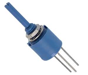
A digital potentiometer is digital equivalent of variable resistor potentiometer. It is a digitally controlled electronic component with built in IC or a digital to analog converter. It is widely used in instrumentation amplifiers. It has limitation of being restricted to currents of a few milli amperes and voltage in the 0 to 5V range.

Relays

Thursday, September 18th, 2008

Relays

Relays are electronic or electromechanical switches that operate under the control of an external circuit.

Originally when first invented in 1835, electromechanical relays consisted of an electromagnet and a set of contacts. When the electromagnet was energized, it closed the contact by attracting a lever held by a spring. When no current is flowing through the circuit, the electromagnet got demagnetized and the spring pulled back the lever and the circuit was left open. This type of relay was widely used in devices such as calling bells.

CP Clare Relay

CP Clare Relay

A special type of relay is a reed relay in which the contacts are enclosed in vacuum tubes in order to protect them from atmospheric corrosion. The operation is otherwise similar to electromechanical relays.

More recently solid state relays have come into vogue. Solid state relays are electronic components similar in function to electromechanical relays. Though initially used for low current applications, these relays are available nowadays for handling currents up to 1200A. They consist of circuits involving transistors and resistors. They have no moving parts and hence no wear out and operate much faster than electromechanical relays.

Relays are widely used in many electric and electronic control applications like overload protection of motors (circuit breakers), temperature / pressure regulators in refrigerators, railway signaling, power systems, starter for automobiles, machine tools etc. As electronic components relays are used in modems and audio amplifiers etc. Modern relays are activated by microprocessor or programmable logic controllers that have the operation logic built in.

What is an old Iomega Zip Drive good for?

Wednesday, September 17th, 2008

Apparently, quite a lot! Take a look as a rescued Iomega Zip Drive becomes a lot more useful than it ever was!

With just a few tools, some electronic components and some outside the box ideas, you can turn a zip drive into, among other things, a marionette!

What Happens to Old Electronic Components and Boards?

Tuesday, September 16th, 2008

We came across this blog post the other day and thought it was worth bringing here.

Here’s an excerpt:

Yesterday I had the opportunity to shoot video in a facility that is the largest company in America that recycles the glass from electronics and computers. The men who own this company, built the machines that separate and break up the glass, themselves.

Electronic products and computers are torn apart. The plastics are sold to one vendor while the electronics and circuit boards are sold to another. The glass fragments are then shipped to companies that melt it down and produce new glass.

I was impressed by how much of the material is able to find new life, rather than to be dumped into a landfill where it would simply sit for all time.

I hope that he’ll update his blog when this segment is aired – I’d love to see the whole process!

How to Use an Analog Multimeter

Monday, September 15th, 2008

How to use an Analog Multimeter
…it’s simpler than you think!

Multimeters are inexpensive and easy to operate, making them very popular. They are very commonly used as devices for electronics circuits testing. Multimeters are categorized into two different types – analog and digital. While the internal circuitry and operation of both are very different, their usage is more or less similar.

Analog multimeters have been in use for a long time and are very flexible in their operation. An analog multimeter can be used for testing a number of electronic components and parameters such as resistance, voltage, current, to name a few.

If you are using an analog multimeter, the first step is to switch the multimeter on. Next, the probes (or the leads) need to be inserted in to their correct positions. There can be a number of connections that can be made, and depending upon what is to be connected, the right positions should be determined. Care should be taken to not insert the leads in to a low current position, if high current is to be measured.

Next step is to set the center switch or knob to the required measurement type and the proper range. The range selected should be higher than the anticipated value. If the value is not known then the multimeter should be set to maximum and the range accordingly decreased afterwards. This ensures that the meter does not get overloaded. The range should be optimized for getting the best reading possible.

Once the reading has been taken, it is good practice to place the multimeter probes in to the voltage measurements sockets with the range set to maximum voltage. This ensures that even if the multimeter is accidentally connected, there is no damage to the multimeter or other electronic components of the circuit. Or if the reading is complete, then the multimeter can be switched off.

How to Read Capacitors

Thursday, September 11th, 2008

Capacitance Values – and How to Read Them

Capacitors are used in a wide range of electronic components and circuits. They form an integral part of electronics. The capacitance of capacitors is measured in a unit known as Farads, represented by the letter ‘F’. A capacitor that has higher capacitance can be used for storing more charge as compared to one with a smaller capacitance value.

One Farad is a very high value for capacitance and usually smaller units are used, namely pico farad, nano farad etc. And as the capacitors are physically very small in size, their capacitance needs to be identified with a code mentioned on the capacitor itself. The exception to this is electrolytic capacitors that are big enough to have the capacitance value written directly on them.

Ceramic and film capacitors usually have a coded value marked on them. If the value marked on them is a two-digit whole number, then the capacitance is equal to the value mentioned in pico Farads. Thus a code of “10” implies that the capacitance is equal to 10 pico farads.

A three-digit whole number includes the first two significant digits, and the third digit as the multiplier (indicating the number of zeroes), and gives the value in pico Farads. Thus a code of “104” means, 10 multiplied by 10,000, giving the capacitance as 100,000 pF or 0.1 uF.

If a decimal number is used as the code on the capacitor, then the capacitance is equal to value mentioned in micro Farads. For instance, “.1” mentioned on the capacitor would imply 0.1 uF.

Finally, a whole number followed by the alphabet ‘n’ means the capacitance is equal to value mentioned in nano Farads.

In addition to the capacitance, the code on these electronic components can also be used for indicating the tolerance, voltage, and temperature properties.

470pF 3000V Capacitor

470pF 3000V Capacitor

In the example above, the capacitor reads:

471M

3KV

The 471 is deciphered as 470pF; M=20% tolerance; 3KV=3,000V

Here are the codes for tolerance:

B +/- 0.1pF
C +/- 0.25pF
D +/- 0.5pF
E +/- 0.5%
F +/- 1%
G +/- 2%
H +/- 3%
J +/- 5%
K +/- 10%
M +/- 20%
N +/- 0.05%
P +100% ,-0%
Z +80%, -20%

What is Transistor-Transistor-Logic – TTL?

Sunday, September 7th, 2008

TTL Transistor-Transistor-Logic

TTL Transistor-Transistor-Logic


TTL or Transistor-Transistor Logic is a type of digital circuit that is made from BJT or bipolar junction transistor along with resistors. Both the amplifying function and the logic gating function are carried out through transistors, thus the name transistor-transistor logic.

TTL is used for many applications like industrial controls, computers consumer electronics, test equipment, synthesizers and more. The TTL designation is also used in some places to imply ‘compatible logic levels’ even if they are not directly associated with transistor transistor logic circuits.

James Buie invented the Transistor Transistor Logic in 1961 and the first Transistor-Transistor Logic devices were made in 1963 in Sylvania. These devices were called the “Sylvania Universal High-Level Logic family” and were used within controls for the US Phoenix missile. In 1964 Texas Instruments produced ICs of 5400 series and later on, the 7400 series which made the Transistor-transistor Logic devices popular amongst electronic system designers. The 7400 series went on to become the industry standard. Many companies like AMD, Motorola, Intel, Fairchild, Siemens, National Semiconductor made compatible parts.

The TTL circuits were low cost which made them highly practical for using digital techniques in tasks which were earlier done through analog methods. One of the first computers that was built, in 1971, made use of the transistor transistor logic instead of a microprocessor chip which at that point of time was not available. With time incremental improvements in power consumption and speed were made, and the last popular series was the 74AS/ALS Advanced Schottky was made available in 1985.