Monthly Archives: November 2013

Our top selling cables for October

Here are some of the top sellers on the West Florida Components web site for October:

Shielded Audio Cable 3.5mm Stereo Male to Male Plug 6 ft

Audio systems are connected to various devices such as MP3 players, DVD players, speakers, portable CD players, TV tuners, satellite dishes, computer sound cards and camcorders. Depending on the specific use, shielded audio cables come in different lengths. The plug or socket size is usually 3.50 mm. CES makes the cables in 6 ft lengths.

The shielded stereo cables come with suitable male connectors of 3.50 mm diameter for connecting between two terminals. The cables are readily available and can be ordered immediately. The product has a code number of HW144PD. The shielded cables are for connection between different types of terminals, and this cable has stereo male plugs on both ends.

Shielded Audio Cable 3.5mm Stereo Male to Male Plug 10 ft

Special shielded cables for stereo audio systems are made for interconnecting various audio devices. CES makes cables of standard length for connection between various devices. The 10ft cable is the standard size for specific applications when the distance between the devices to be connected is about 10 feet or less. Various audio devices can be interconnected via these shielded cables.

Male to male plug connection cable serve a specific application. The receiving devices are usually CD players, computer sound cards, satellite dishes, TV tuners, and MP players. The plug connectors are of 3.5mm diameter providing male-to-male connectivity. The product is available for immediate delivery.

Shielded Audio Cable 3.5mm Stereo Male Plug to Female Jack 3 ft

The distance between a stereo audio system and the receiving devices varies from location to location. Audio signals can be transferred to receiving devices through shielded stereo audio cables. CES manufactures these cables to suit particular locations limited to 3ft, suitable for interconnecting male plugs to female jacks.

The plug and jack are both 3.5mm diameter standard size for the CES cable. The cable has a part number of HW 146PD. The cable is extensively used for connecting all audio devices including speakers to the audio source. Suitable connectors are provided at either end of the cable, so that interconnections may be made between the male plugs and female jacks.

Shielded Audio Cable 3.5mm Stereo Male Plug to Female Jack 6 ft

Audio devices such as computer sound cards, satellite dishes, DVD players etc., require a very special cable for connection to the audio source. For the stereo sound to be reproduced without distortion and without any external noise, shielded cables are used for special audio application. 6ft cables are available that are manufactured by CES with a part number of HW147PD.

The plug and jack is 3.50mm in diameter. The cable has been made especially for connecting the stereo male plug to a female jack, with a separation of 6ft or less. It is readily available for shipping.

Shielded Audio Cable 3.5mm Stereo Male Plug to Female Jack 10 ft

Audio systems require special cables for interconnecting various devices. They may be located at some distance from the system. Manufacturer CES produces 10ft shielded stereo audio cables for such connections with part number HW 148PD. It is suitable for connecting a stereo male plug to a female jack within a distance of ten feet or less.

The 10ft cable comes with connectors of 3.5mm diameter provided at both ends of the cable. The connectors are suitable to interconnect a male plug to a female jack. Any stereo device such as the DVD player, computer sound cards can be connected using these cables.

Small Alligator Clip Test Lead Set of 10 Cables 2ft

For connecting several items between various devices, CES produces small test lead sets. The lead has alligator clips. It consists of a set of ten cables and is usually 2ft in length, with a product code of HW149PD. The clips are of 1-inch in size and usually white. The lead is very useful in testing circuit designs.

It is also used for testing services. The ten cables forming one set comes in different colors for easy identification. Usually two cables are of the same color. The identifying colors used are red, black, green, etc. The connecting set is readily available.

Large Alligator Clip Test Lead Set of 10 Cables 2ft

Test leads need to be suitable for connection to the terminals of different sizes. CES produces large test leads for such connections with a part number of HW151PD. The test lead has alligator clips and it comes with a set of ten cables. The clip size is 1 ¾ inches. It can be used for any testing service or any circuit designs.

Each set of the test lead comes with ten cables of different colors. The difference in colors makes for easy identification while testing. Each set of two cables in the ten set lead is of the same color. Colors of yellow, green, white, black and red are used.

DADPTAT9M25F DB9 Male to DB25 Female Adapter

Computer circuits need special adapters such as for printers, etc. Such male to female adapters are manufactured by Microhite, with product number of DADPTAT9M25F and the product code is GS14APF07. The adapter has gold plated contacts and the body is molded PVC. It is provided with a shield of Aluminum Mylar foil.

For easy connection, the adapter has extra-long thumbscrews. The adapter is specially made for converting a DB9 male terminal to a DB25 female terminal. The adapter weighs 1.70-ounces.

DB15F DB15M Adapter Connector

Some connectors will need adapters to be made suitable for different type of connection. A female connector may be needed for suitably connecting to a male connector depending on the circuitry. WFCP makes such suitable adapter connectors with product number G515APF07.

The adapter connector is a 15pin device and is lightweight at 1.13ounces. The part number is DB15F/DB15M manufactured by TTI. Its dimensions are 1.55 inchx1. 58inch x 0.58inch.

12 Gauge 2 Pin Quick Disconnect Bullet Leads Cables 1 Ft

quick disconnects
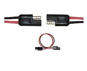
Two pin quick disconnect bullet leads are normally used for connections where polarity is critical. The cables come with a 2-pin molded connector. It also has a 2-pin bullet lead for quick disconnect. The cable is 12 inches long and its leads are color-coded. The pins have a positive grip while providing instant connection or disconnection as required.

The cable is made of a 12AWG wire. The bullet type connector is suitable for male to female terminal connections. Suitable locking mating ends are provided so that proper connection is maintained under all conditions. CES produces these cables with the product number of 1376APF09.

What Is An Electronic Load And Where Do You Use It?

Power supply manufacturers need to test their products dynamically. Instead of using fixed-resistor banks of different sizes, electronic loads allow them to simulate easily and quickly various power states. Using an electronic load, large ranges of power sources such as converters, inverters, UPSs and electromechanical sources such as batteries and fuel cells may be tested. For varying loads, electronic loads are easier to use and provide a much higher throughput compared to fixed-resistors.

For example, a handheld device may have to be tested for sleep, power conservation and full power modes. These are easier to test using a single electronic load, but may require several combinations of fixed-resistors. Additionally, an electronic load may be programmed to represent closely a real environment for a power source. This may take the form of modulation to improve the performance of power supplies by providing a faster transient response as compared to a standard power supply.

An electronic load usually consists of a bank of power transistors, power MOSFETs or IGBTs mounted on a suitably sized heat sink, and cooled with fans. An electronic circuit governs the amount of current that the power devices can draw from the power supply on test. To protect the power devices from damage, electronic loads usually have a pre-settable power limit. The manufacturer usually provides a power curve for the safe operation of an electronic load. The user must be aware of the simultaneous maximum voltage and current that can be applied to the electronic load to ensure the electronic load is not overpowered.

It is important to select a suitable electronic load for the testing. For example, a power supply rated for 12V and 30A, may never be operated at 12V and 30A continuously. While testing, the operator may run it at 12V and 5A and then at 3V and 30A. That means an electronic load of 90-100W is sufficient to test the supply.

To improve the performance of a power supply, an electronic load may be used as a high-speed current modulator. In such cases, only a fraction of the power rating of the power supply is required. When the current is modulated to the highest level, the voltage across the load is likely to be very low. As the current is modulated off, the voltage rises to its maximum. Usually, if the modulation of the current is from zero to some maximum, the load power required is one-quarter of the operating voltage times the current rating with some margin added.

Electronic loads are very useful for dynamically testing power sources. In this form of testing, the current is quickly pulsed between two states, simulating a possible sleep mode and a full power mode of a device. This pulsing can be as fast as 20,000 times a second.

Another requirement that electronic loads are adept at is low voltage testing. Although most electronic loads will refuse to operate when the applied voltage is below 1V, there are some models, which perform comfortably down to 0.6V. This is a very useful feature when testing fuel cells where the operation at low voltages is crucial.

Home Protection with Raspberry Pi

Planning to go on a vacation, but afraid of who will look after your home for you? Worry not, for the mighty Raspberry Pi (RBPi) is here. Not only will RBPi look after your entire house, it will send you an email of what is happening in your home and let you see it on your mobile or on a PC. How cool is that?

Most alarm systems incorporate three primary sensors. The first is a temperature sensor to detect the rise in temperature in case of a fire. The second is an intrusion detection sensor to detect if an intruder has gained access to the insides of the house and third is a motion detection sensor. Apart from these primary sensors, you may add smoke detectors and cameras according to your necessity.

The software consists mainly of a database to store all the events with a time stamp, a dashboard to display the status of the sensors, configure them and to program the alarm system. The Raspberry Pi also acts as a web-server to send email alerts and to display the dashboard on a remote computer or Smartphone.

Depending on the size of the home, its vulnerability and the number of sensors being used, you could divide the area into a number of zones. This makes it easier to arm the sensors belonging to a specific zone. For example, a door and few windows of your home may be facing a busy street during the day and you may decide not to arm the sensors in this zone in the daytime. As night falls, the street gets deserted and you may want the sensors in that zone to be armed for the night.

Dividing the home into zones also has the advantage of knowing in which area or areas the alarm has been triggered. The camera for that zone can then be switched on to assess the situation visually.

Since RBPi runs on Linux, and Linux multitasks very well, the software runs in the background. The software is programmed to wake up RBPi about once every minute and check in on each of the armed sensors in all the zones. If there is no activity, it simply updates the logs for the database and the dashboard and goes back to sleep.

If a sensor trips, or generates an activity, Raspberry Pi records it in its logs, and sends you an email with the details. The dashboard then indicates the alarm condition in the zone where the alarm originated. You have a choice of turning off the alarm after checking it out.

You can login to the server from a remote PC using a username and a password. The web-browser will display the dashboard and a green button lets you know that the RBPi is running your home alarm software and is transmitting the information from the sensors. If the alarm system goes down for some reason, or there is a problem with the connectivity between the Raspberry Pi and your computer, this green button will turn red within a minute. You can now proceed to test, arm or disarm the sensors in each zone. For details of software and setup, refer here.

Gardening with the Raspberry Pi

Many of you may be garden enthusiasts and would welcome the idea of automating some of the maintenance requirements of your plants. For example, keeping tabs on the quantity of water that is required by the plants based on the moisture in the soil, the available sunlight and the environmental temperature might be easy for an experienced gardener. However, gardeners who have just started gardening find it a difficult equation to balance. Even an experienced gardener may have to depend on a novice if taking leave from his garden for a few days.

With a Raspberry Pi (RBPi), most of the above gardening issues can be fixed. The Raspberry Pi can take care of the garden’s watering requirements based on a few environmental measurements. This can bring relief to an experienced gardener forced to leave his beloved plants for a few days. The novice gardener can quit worrying if he is starving his plants or drowning them in water. This is how Devon approached the problem with his Raspberry Pi.

Avid gardening enthusiasts know that too much water to a plant can be as bad as too little. For the Raspberry Pi to determine how much water should be delivered to the plant, it is necessary to know how much moisture is present in the soil in the first place. That, combined with the temperature and the amount of available light can let Raspberry Pi control the pump that delivers the water to the garden.

Since Raspberry Pi is not capable of measuring analog signals that most sensors put out, an Analog to Digital Converter attachment is necessary. For this, using the MCP3008 ADC is a good choice since it allows eight sensors to be used at a time. For sensing the amount of sunlight available, a Light Dependent Resistor or LDR is useful. To measure the ambient temperature with some amount of precision, a temperature sensor such as the TMP35 or TMP37 will do. For sensing humidity in the soil, a homemade humidity sensor using a few long metal nails will be fine.

All the sensors will need a DC voltage supply and a return ground connection, with the signal from each sensor going to one of the channels of the ADC. The 3.3VDC from the Raspberry Pi board is good enough for the sensors. While only one temperature sensor and one LDR is enough, you may need more than one humidity sensor, depending on how big your garden is.

The humidity sensors check the resistance of the soil between a pair of probes inserted into the ground. As the soil dries up, the resistance increases between the two probes of the humidity sensor. If several such probes are placed at different places in the garden, the Raspberry Pi has a fairly good idea of the state of dryness of the soil in the garden.

The final and most important part of the entire system is the pump that delivers water to the garden. Using a tank and a submersible pump eliminates a whole bunch of issues that many gardeners face. You can experiment with drip-irrigation also if you like the idea. Devon has kindly shared the software and the code used, and you can download them here.

Sensing humidity using advanced technology

An approaching thunderstorm creates a very stuffy environment with oppressively heavy moisture in the air. The presence of water in the air is termed as humidity and this largely affects human comfort. The amount of water vapor influences many physical, chemical and biological processes. In industries, measuring and controlling humidity is critical since it can affect not only the health and safety of personnel, it can affect the business cost of the product as well.

Sleep apnea leads to repeated cessation of breathing during sleep. People, who suffer from sleep apnea, have to wear a mask to prevent nasal collapse. The mask is connected to a Positive Airway Pressure machine that sends pressurized air through the nasal passage of the patient, to prevent it from collapsing. It is important to monitor the humidity of the air the patient receives, keeping it at the appropriate level of comfort to allow the patient to sleep comfortably.

Traditionally, humidity or relative humidity was measured with the wet and dry bulb hygrometers. This method is neither accurate nor convenient in the industrial environment. With advancement in technology, solid-state devices are now available, which measure humidity with very high accuracy, repeatability and interchangeability. Solid-state humidity sensors are generally of two types, capacitive and resistive.

In resistive type humidity sensors, the resistance of the element changes responding to variations in humidity in the environment. The construction is in the form of two intermeshed printed combs, made of a thick film conductor of a precious metal such as gold or ruthenium oxide. The two combs form two electrodes, the space between them being filled with a polymeric film. This film has movable ions whose movement is governed by humidity. The film thus acts like a sensing film whose resistance changes with change in humidity.

The capacitive type of humidity sensor has an Alumina substrate on which the lower electrode is formed using either gold or platinum. A dielectric polymer layer such as thermoset polymer is then deposited on the lower electrode. This layer is sensitive to humidity. On top of this polymer layer, a top electrode is placed, and this is also made of gold or platinum. The top layer is porous and allows water vapor to pass through into the sensitive PVA layer. Moisture enters or leaves the sensing layer until the vapor content is in equilibrium with the environment. This sensor is therefore a type of capacitor whose capacitance changes with the change in humidity.

The arrangement of a hygroscopic dielectric material sandwiched between two pairs of electrodes, forms a capacitor whose value is governed by the dielectric constant of the hygroscopic material and the sensor geometry. At normal room temperatures, the value of the dielectric constant of water vapor is about 80, which is much larger than the constant of the sensor dielectric material. Therefore, as the sensor absorbs water vapor from the environment, it results in an increase in the capacitance of the sensor.

Both the resistive type and capacitive type of humidity sensors are available in the form of small surface mount SMD packages, and pre-calibrated to simplify, speedup manufacturing and reduce the cost for Original Equipment Manufacturers.

What Is Back EMF And What Does It Do?

Newton’s third law talks about conservation of energy. In the electromagnetic world, this is best manifest in the form of Lenz’s law, which states – “An induced electromotive force (emf) always gives rise to a current whose magnetic field opposes the original change in magnetic flux.”

To understand it in simple terms, the wire in the diagram experiences a downward force because the magnetic field of the permanent magnet reacts with the magnetic field created by the current flowing in the wire. If you were to reverse the direction of flow of current in the wire, the wire would move up instead. This is also called the motor effect, since this is the way motors work.

The wire (formed into a square loop), experiences a torque because the current flowing in the two arms of the loop are not in the same direction, causing the forces on the wire to be in opposite directions. The torque turns the wire loop. By having many such wire loops in its rotor, the motor is able to turn heavy loads.

Since there are two opposing magnetic fields operating when the motor turns, the speed of the motor is governed by the balance between the two. However, the two magnetic fields are never equal, as there is the mechanical friction of the bearings to be overcome to keep the motor rotating, and the difference between the two is called the Back EMF.

Although Back EMF is a good and necessary phenomenon that makes running of motors possible, it assumes menacing proportions in the operation of relays and solenoids. A relay or a solenoid consists of a coil or a large number of turns of wire on an iron core. One of the properties of such an arrangement is the coil stores energy when current passes through it. This, by itself, is nothing to worry about, unless the current is suddenly stopped. This is where you may want to read Lenz’s law again.

When the switch is opened, the current from the battery stops flowing instantly. However, the energy in the relay or solenoid “opposes the original change in magnetic flux”, which is now trying to collapse. The coil can do this only by keeping the current flowing across the gap in the switch. The only way it can do this is by creating a Back EMF high enough to generate an arc across the gap. The arc is sustained until the energy in the inductor dissipates.

Now, arcs in any form are dangerous, and the best way of handling them is to quench them as quickly as possible. In normal operation, a semiconductor switch such as a transistor replaces the resistor and switch shown, and is turned on or off to operate the relay. An arc can blow or damage a transistor in the fraction of a second.

The solution is rather simple. A flyback diode (also called a free-wheeling diode / snubber diode / suppressor diode / catch diode) is connected across the solenoid. When the switch is closed, the diode remains reverse biased and inactive. When the switch opens, the diode conducts to let the inductor current flow in an alternate path and limit the Back EMF to the forward voltage drop of a silicon diode (0.7V).