Monthly Archives: September 2014

Pulse Ranging Technology Sensors Can Now Measure Distance

Radar measures the distance of an object by bouncing bursts of high frequency waves from the surface of the object and sensing the time it takes the echo to return. Pulse Ranging Technology or PRT sensors use a similar technique, but instead of using radio waves, they use bursts of light. The sensor emits bursts of light that travel to the object, bounce off its surface and return to the sensor. A processor in the sensor measures the time of flight of the light pulse and calculates the distance to the object.

PRT sensors emit light pulses of high-intensity at rates of 250 thousand pulses every second. The delay between the emission of light and its recapture increases with distance. Distances can also be measured by sensing the difference in phase shift of the reflected light from other types of photoelectric time of fight sensors that emit continuous light beams. The returning beam of light undergoes a change of phase because of reflection, and the difference in phase is a measure of the distance travelled by the light beam. However, a PRT sensor is superior in performance to other types of sensors.

Since a PRT sensor uses a pulsed laser diode, higher currents can be pumped into the laser source, resulting in light of higher intensity as compared to sources emitting continuous light. Light from a PRT sensor can be up to a thousand times more intense than that from other sources, which means they can easily detect objects further than 300 m.

High intensity light pulses from PRT sensors are not harmful to eyes. Although the light is intense, PRT sensors are off for longer periods that they are on. Therefore, in reality, PRT sensors emit very low power at any time compared to sensors sending out continuous light beams. In the market there are several PRT sensors certified as Class 1 laser products or “eye-safe.”

As pulsed light is easy to differentiate, PRT sensors are immune to other nearby photoelectric sensors, lighting and even sunlight. While sensing pulsed light, the PRT sensors can eliminate interference and crosstalk. On the other hand, sensors that use continuous light beams find light from stray sources often interfering with their readings.

PRT sensors are very useful in measuring continuously changing positions of the target. For example, they can monitor the stack height of metals; check if a container has been filled up to a specified height; and position a load or a product properly. They are good in preventing collisions of cranes, gantry and conveyors. Some PRT sensors can convert the distance measurement to streams of binary digits via Profibus, Ethernet or IO-Link, while some can output analog signals as well.

PRT sensors are useful not only for distance measurements, but also for detecting the presence/absence of objects. For example, they can verify rack occupancy in warehouses, detect stacks or panels within a defined window, tell when spools or rolls are either empty or full and check the height of a forklift truck. Moreover, designers can set the range at which the sensor will start detecting objects.

Why Do We Need Amorphous Iron Motors?

<Occasionally, engineers need motors that must operate at high frequencies but with a high energy-efficiency. At high frequencies, the magnetic fields inside the motor change rapidly. Normal CRGO or Cold Rolled Grain Oriented steel has eddy current losses that rise with the increase in operating frequency. Amorphous iron has a special structure that allows it to respond to fast changing magnetic fields without power loss due to hysteresis and eddy currents.

Contrary to popular belief, amorphous iron is not an exotic material and is not hard to come by. People’s interest in this special metal is rising since it has magnetic properties that promote energy efficiency in power distribution equipment and electrical machinery. The properties of amorphous iron make it very useful for electrical equipment.

For example, a commercially available motor made of amorphous-iron has a two-stator permanent magnet brushless configuration. While the rotor has 36 poles, each stator is provided with 54 slots. Green areas show the places where the motor uses amorphous iron. In practice, the motor operates at 1,000 RPM.

As interest in this metal grows, amorphous iron is actually manufactured in huge quantities. Two firms in the world are the major suppliers of amorphous iron. One of them is the Advanced Technology & Materials Co. Ltd., China and the other Metglas in Conway, SC and Tokyo, a division of Hitachi Metals. Of them, Hitachi Metals supplies the major bulk of the 100,000 tons of amorphous iron produced annually.

Amorphous iron is a typical alloy of iron with silicon and boron. Manufacturers make amorphous iron in the form of thin ribbon or foil of 25-micron thickness. The process used to manufacture the iron sets the special form factor. Molten iron is made to drip onto a wheel made of pure molybdenum. Since the molybdenum wheel is maintained at a precisely controlled temperature, the iron hitting the wheel quenches very quickly. In fact, the temperature of the molten iron drops at a rate of nearly a million degrees every second. Such an extra-fast rate of quenching freezes the molecules of iron before they have a chance to form crystals. That gives the iron its amorphous structure, which has a much less orderly form that the more popular crystalline iron.

Since the extra-fast rate of quenching has to occur throughout the internal molecules of the iron, the harvested iron from the molybdenum wheel is necessarily thin. If the thickness of iron increases beyond 25-microns, the internal molecules would not cool so fast and would have time to form crystals. The resulting metal would not have uniform amorphous quality.

Amorphous iron, with its disorderly structure responds to changes in magnetic fields far more readily than does iron in its ordinary crystalline form. The super thin nature of the amorphous iron limits the formation of eddy currents, which are an additional source of loss. Overall, amorphous iron exhibits higher efficiency because of very much reduced power loss when working in a given magnetic field strength as compared to that of the regular type of crystalline iron.

You can roll up your TV

Currently you can carry your TV in your hand as you travel. Of course, the screen size of your smartphone may not be as big as the TV in your living room. The day may not be far off when you could just roll up your large-screen TV, put it under your arm and walk out of your room.

LG has demonstrated a completely flexible large-scale display of size 18 inches. The display is flexible to the extent of being rolled up into a 3 cm scroll for transport. You can unfurl the transparent display, hang it on the wall, lay it flat on a desktop or mount it in a conventional frame. LG is confident of unfurling a 60-inch variant of the display by 2017 and promised that they will give it even higher transmittance.

NPD DisplaySearch of LG has been working for some time now to produce displays on flexible substrates culminating in the commercialization of the flexible 18-inch large-scale display. They plan to bring out smaller flexible displays over the next couple of years. Although these may be of the size used in smart watches, they will be one-time flexible until put behind a curved glass cover. However, to have them flex in any shape at any time is still some way off.

Flexible displays are usually made from organic light emitting diodes (OLED). These are deposited on a transparent substrate. Since they do not require a backlight, they can display graphics such as schematics in mid-air, being visible from both sides. LG successfully demonstrated this mid-air display capability while at the same time proved that they have mastered the basic technologies behind manufacturing rollable transparent displays.

However, commercialization of the technology still faces substantial hurdles. The OLED needs to be protected from oxygen and moisture – both of these reduce the life of the display. LG expects active OLED will bring in revenues to the extent of $23 billion by 2020, coming mostly from mobile phones and smartwatches with flexed and fixed displays. However, there are production challenges yet to be solved. Protecting a display from the environment is no big deal as encapsulating a curved display can be fixed in glass and metal. However, a backplane is yet to be developed that will reliably prevent damage to the OLEDs while remaining sufficiently flexible.

If you have visited the IMAX Theater, you can appreciate the wraparound immersive experience that a flexible display brings. Apart from making mobile devices easier to carry, the curved screen technology can provide auxiliary screens that help to transport and display large diagrams such as building schematics and blueprints.

LG’s 18-inch prototype has a configuration of 1200×800 with nearly one million pixels. It has a curvature radius of 30R, meaning you can roll it into a scroll of a little over an inch, while it is still working and there will be no damage to the display. LG is planning for a 60-inch display with an increased curvature radius of 50R.

If LG succeeds in developing the transparent polyimide backplane for the display, someday, refrigerators will have transparent doors so you could see the food inside, while reading the temperature and seeing advertisements.

What is an H-Bridge?

Those who are into robotics know that robots, just as humans do, also need to suddenly change course when they run into an obstacle in their path. Changing course while walking may not be a big deal for humans, but for robots, and especially for those who design them, it is sometimes a serious challenge.

For example, consider a robot that is moving towards an obstacle, which it has to avoid and proceed on a parallel path. A robot with two wheels will need to stop moving as it reaches the obstacle, then pivot on one wheel by a certain angle and move forward until the obstruction no longer bars its way. Then it has to stop again, pivot back on the other wheel by the same angle it had turned earlier and move forward. If the robot is required to go back to its original track, it has to pivot once again. The entire exercise gets more complicated if the robot has more than two wheels; clearly, robotics is not for the faint-hearted.

Most movements in robotics involve DC motors and moving a robot backwards requires the DC motor to run in reverse. This is accomplished by switching the connections of the motor to its power source so that it now connects in a way opposite to its normal manner. Doing this causes the current flow in the motor to reverse, making it rotate in the opposite direction. However, it is impractical to manually disconnect the wires of several motors and reconnect them in a moving robot. That job is best left to H-bridges.

An H-bridge is a circuit that looks very similar to a capital H. It has four switching elements at its corners, with the motor forming the cross bar. The only difference are the top and bottom bars – these are not part of the alphabet H. Traversing clockwise, the four switching elements are called – high-side left, high-side right, low-side right and low-side left. The top bar connects to the positive terminal of the power supply/battery and the lower bar connects to the ground or the negative terminal of the power supply/battery.

You run the motor by turning on a pair of switches. For example, if you turn on the switches high-side left and low-side right, the motor will turn, say, in a clockwise direction. If these switches are turned off and the other pair is switched on, they connect the motor to the supply in reverse and the motor rotates counterclockwise.

While the switches are turned on in pairs, those on the same side must never be turned on simultaneously. For example, if the two switches on the left or the two on the right were to be switched on together, they would create a direct short between the terminals of the power supply/battery, bypassing the motor altogether.

This phenomenon is called shoot through, and if your power supply or battery has no short-circuit protection, it may cause a premature failure of the source including irreparable damage to the switches. Typically, the rating of the switches must match the rating of the motor – powerful motors operate on high currents and the switches must be capable of handling those currents. In practice, the switches are power MOSFETs or IGBTs.

What is a 4-20 mA Current Loop?

The pre-electronic industry used pneumatic controls. Compressed air powered all ratio controllers, temperature sensors, PID controllers and actuators. The modulation standard was 3-15 pounds per square inch, with 3 psi standing for an active zero and 100% represented by 15 psi. If the pressure went below 3 psi, an alarm would sound.

Electronic controls made their debut in the 1950s. A new signaling method with 4-20 mA current emulated and replaced the 3-15 psi pneumatic signal. As wires were easier to handle, install and maintain, current signaling quickly gained popularity. In contrast, pneumatic pressure lines and energy requirements are much higher – you need a 20-50 HP compressor, for instance. Moreover, with electronics you can add more complicated control algorithms.

The 4-20 mA current loop is a sensor signaling standard and a very robust one. Current loops are the favored form of data transmission method because they are inherently insensitive to electrical noise. In the 4-20 mA current loop, the signaling current flows through all the components. Therefore, the same current flows even if the wire terminations are not perfect. All components in the loop drop some voltage because the signaling current flows through them. However, the signaling current is unaltered by these voltage drops as long as the power supply voltage remains greater than the sum of the individual voltage drops around the loop at the maximum signaling current of 20 mA.

The simplest form of the 4-20 mA current loop has only four components –

− A DC power supply
− A 2-wire transmitter
− A receiving resistor to convert the current signal to a voltage
− A wire to interconnect all the above

Most 4-20 mA loops use 2-wire transmitters, with standard power supplies of 12, 15, 24 and 36 VDC. There are also 3-wire transmitters with AC or DC power supplies.

The transmitter forms the heart of the 4-20 mA signaling system. The transmitter helps to convert physical properties such as pressure, humidity or temperature into an electrical signal, a current, proportional to the physical quantity being measured. In the 4-20 mA current loop system, 4mA represents the lowest limit of the measurement range, while the 20 mA represents the highest limit.

Since it is much easier and simpler to measure voltage than it is to measure current, typical current loop circuits incorporate a Receiver Resistor. This resistor helps to convert the current into a voltage, following Ohms Law (Voltage = Current x Resistance). Most commonly, the resistor used in a 4-20 mA current loop is 250Ω, although some engineers use resistances of 100Ω to 750Ω, depending upon the application. When using 250Ω, four mA of current will produce a voltage of one VDC across the resistor, and 20 mA will produce five VDC. Therefore, the analog input of a controller can very easily interpret the 4-20 mA current as a 1-5 VDC voltage range.

The wire connecting all the components of a 4-20 mA current loop has its own resistance expressed in Ohms per 1,000 feet. Some voltage is dropped across this resistance of the wires according to Ohm’s Law and has to be compensated by the power supply voltage.

The major advantages in using 4-20 mA current loops are their extreme immunity to noise and power supply voltage fluctuations.

Automation Controller Uses Raspberry Pi Compute Module

Remote control has a new face. Based on the tiny credit card sized single board computer Raspberry Pi or RBPi, Techbase has designed a Linux-based ModBerry automation computer. They back it up with an iMod cloud platform. ModBerry is all about remote control.

This version of RBPi was introduced lately and known as the Compute Module or Computer-on-Module. People in Poland have taken up the RBPi Compute Module wholeheartedly and turned it into ModBerry. Initially, the Polish startup Sher.ly started with Sherlybox, a private cloud storage device based on the RBPi COM (Compute Module). Now, Techbase, the industrial computer manufacturer from Gdansk, Poland, has based their automation computer ModBerry 500 on the RBPi COM.

The RBPi COM is a part of the development kit that Farnell Element 14 and RS Components have released recently. The kit also contains a separate baseboard. Later plans include selling the module independently.

Techbase is already in the market with numerous Linux-ready and Linux-based automation controllers and industrial computers. Techbase supports some of its computers with its cloud-based iMod, iModCloud and iModWizard, which also provide Software-as-a-service or SaaS applications. This includes its telemetry computer iMod-X1000.

In contrast, Sherlybox is a private crowd based on local storage. With the iMod ecosystem, users can store data and control several iMod compatible computers via a cloud platform. By combining ModBerry 500 and the software from iMod, users have access to applications in the general automation market and intelligent buildings. According to Techbase, they can also monitor and control wind farms, GSM base stations and power stations. Users can set up their devices as protocol converters, telemetry modules, data loggers, servers, MODBUS routers, PLC devices, SNMP agents and many more.

The iMod system is a versatile arrangement offering multi-level, user access cloud management via configuration files. According to Techbase, its iModWizard makes it unnecessary for the user to possess any programming knowledge. Users can freely create different user profiles such as end-user, administrator and system designer. Additionally, iModCloud helps users to update software and configure services.

With iModCloud, users have custom-based actions including notifications and management, which are extremely important for remote control. Users can see the location of GPS-enabled devices on maps provided as part of data visualization capabilities. Users can access their data on smartphones or tablets. Techbase assures security via SSL certificates and encrypted VPN communication.

The ModBerry 500 operates on a wide-ranging 9-24V AC/DC supply. It is available in commercial as well as in extended models, which can work between -25 and 80°C. The physical dimensions are 106x91x61 mm. The ModBerry 500 gets its computing power from the RBPi COM, which provides it with the 700MHz ARM11 Broadcom system-on-chip processor running Raspbian Linux. The module also shares its 512MB RAM and its 4GB NAND flash storage with the ModBerry.

The hardware features of the ModBerry include several real-world ports such as a USB 2 host port, a 10/100 Ethernet port, a slot for SIM card, audio out and a user programmable button. Other ports include an HDMI port and a reset button. There is also a pair of RS-232 and RS-485 ports, CAN ports and a 1-wire bus.

For more information on ModBerry 500, refer to this website.

Scalable Electronics – the automakers choice

Those who have watched the movie Total Recall may recall seeing automobiles driven by robots. Passengers need to mention only the destination and sit back and enjoy the ride. The robot drives them to their destination. Well, those days may not be far off in reality. Automobile development is proceeding with technological advances that allow vehicles to control themselves to the extent of driving with minimal or no human assistance.

However, such developments cannot happen overnight. Then again, there is the question of people accepting such advancements. Therefore, automakers are continually announcing new developments in automated features in their upcoming models. For example, some vehicles are already equipped with automated monitoring and warning features. The plan is to introduce semi-autonomous models initially and then phase in the fully autonomous vehicles to be driven on the roads along with other traditional vehicles.

Such innovations in the auto industry involve advanced electronics for sensing, recognizing, deciding and acting upon changes in the road environment. While introducing new automated features, automakers have to face several factors that affect decisions about the electronic components and systems. Typically, these factors include performance, size, cost, power requirements, reliability, availability and support. In addition, automobile systems need to evolve from year to year, proceeding with car model changes and bringing in feature additions and improvements in the sensing technology. This requires the electronics to be scalable.

Scalable solutions offer the best options to carmakers. Scalable technological solutions help to keep the carmakers stay on track when offering new automated capabilities while balancing the requirements in the overall system design. To make self-driving cars a reality, auto manufacturers need improved electronic technologies for sensing, communications, sensor fusion, high-performance processing and many other functions. As car models change and improved sensors and additional features increase the data load, autonomous vehicle controls will have to be scalable, as this is a multi-year evolution.

Safety, convenience and efficiency are three things that all owners of vehicles look for. Increasing autonomous control in vehicles will help in eliminate several types of human errors that cause most accidents. Not only will that save lives, but also reduce injuries to a great extent and minimize property damage. Imagine cars driving themselves while chauffeuring children, the disabled and the elderly. People will be free to take up other activities while traveling. You can call your car to pick you up, without needing a human driver. Autonomous operation of vehicles will allow them to be more fuel-efficient, while more vehicles can travel safely together on roads. This will save energy and reduce costs on infrastructure.

All the initial automated feature offerings support safety as their top priority. These features are primarily designed to help drivers avoid making mistakes and are termed the Advanced Driver Assistance System or ADAS. As part of scalable electronics, ADAS features will be important elements when carmakers introduce fully autonomous vehicle operations in the future. According to the National Highway Transportation Safety Administration definitions, this introduction will happen in five levels –

• Level 0 – No automation, driver in full control
• Level 1 – Function-specific automation, most of the current modern vehicles are here
• Level 2 – Combined function automation, active cruise control with lane keeping
• Level 3 – Limited self-driving automation, full self-driving but driver can take over control
• Level 4 – Full self-driving automation, driver not required.

Raspberry Pi Radio

Raspberry Pi or the RBPi, the tiny credit card sized single board computer is so affordable that people can easily create single purpose appliances around it. For example, just by adding a small LCD that has a few buttons and a USB wireless network adapter, you can build a self-contained music streamer around the RBPi. This you can move around to any room of the house. The only extra items you need to connect to it are power and speakers or headphones.

Use the Adafruit LCD kit that has a keyboard along with an RBPi. You can select from several versions of the LCD kit: RGB negative backlight, the RGB positive or the more affordable Blue and White. For this kit, you must be prepared for some assembly and soldering. Although the RBPi can be any model, A or B, you will need a 4GB or larger SD memory card. You may use any mobile phone charger, but the charger cable must be compatible with the USB Micro-B connector on the RBPi.

You may connect headphones or amplified speakers to the audio output of the RBPi. Alternately, connect it to the A/V setup in your living room. To connect to the internet, you will require a USB Wi-Fi adapter compatible with the RBPi and of course, an existing wireless network and a working Pandora account. If you have wired Ethernet, you could use that with the RBPi Model B, but that will reduce the convenience of wireless. Finally, you will need a suitable enclosure – one that offers full access to the top of the RBPi board.

You will also need some temporary items only for setting up. These can be removed and do not need to remain permanently attached. To communicate with the RBPi, you will need a monitor and keyboard. Additionally, you may possibly require a powered USB hub, a soldering iron and some solder for assembling the LCD keypad kit.

The Linux OS available for the RBPi has several flavors. For this project, the recommended distribution is the Raspbian Wheezy (official distribution) or Occidentalis (from Adafruit). You may also use any of the other stock distributions along with additional software. Download the OS, uncompress the ZIP file and follow this link to install the OS onto the SD card.

Start by formatting the SD card as a FAT32 file-system and install the OS on it. Next, solder the LCD Pi Plate following this tutorial. House the RBPi in its case. Also, set up a free Pandora account and select your favorite stations.

Once your SD card is populated with the OS of your choice, connect a USB keyboard and a monitor to your RBPi. Insert the SD card in its slot and connect the Micro-B USB cable to the power connector on the RBPi. The other end of the USB cable you can plug into the mobile phone charger, a powered USB hub or simply to the USB port of your computer.

Once you successfully power up the RBPi and navigated past the initial UNIX stuff, you can follow the instructions presented here for the rest of the project.

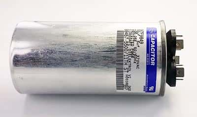
More Italfarad, Ducati & Gentex Motor Start & Run Capacitors in stock!

more motor start capacitors in stock!

You’ve been asking for them – now we have them. We’ve added more values to our motor start and motor run category including some from Italfarad, Ducati and Gentex.

Check out our full selection at https://www.westfloridacomponents.com/MotorStart-RunCapacitors.html.

Need a different value? Ask us, we might be able to get them for you!

Project Firefly – the electric helicopter

A subsidiary of the United Technologies Corp., Sikorsky Aircraft has revealed its innovation at the Farnborough International Air Show – a demonstrator for an all-electric helicopter technology. The actual demonstration aircraft named The Firefly will be unveiled on July 26 at the Experimental Aircraft Association at their AirVenture exhibition to be held in Oshkosh, Wisconsin, USA. Being a part of the world symposium on electric aircraft, the demonstrator is expected to be one of the main attractions.

According to the Director of Sikorsky Innovations, Chris Van Buiten, the objectives of the Project Firefly are –

– Offering proof of principle concept for validating the benefits of an electrically powered rotorcraft
– Developing the technologies for enabling a manned flight of this technology
– Driving future development of improved, state-of-the-art green technologies and practices

The demonstrator is built around an S-300C helicopter. The Innovations team has replaced its legacy propulsion system. In its place, the team has used a highly efficient electric motor, which is controlled by a digital controller from US Hybrid. Power comes from a lithium ion energy storage system made by Gaia. Health information about the aircraft comes in real-time from integrated sensors via a panel integrated interactive LCD monitor. The Eagle Aviation Technologies, LLC, executed the custom airframe modifications and assembly of the demonstrator aircraft.

As the fossil fuel reserves of the world continue to dwindle with increasing demand, the supply/demand cycle is set to increase the operating costs of all vehicles running on such fuel. The aviation industry is particularly vulnerable, with the worst sufferer being the commercial helicopter market – spiraling fuel costs are set to threaten the critical role played by rotorcraft.

Transformations in the propulsion technology have being enabling most of the significant advancements in aviation so far. Electric propulsion technology for rotorcraft is especially exciting because this technology increases the efficiency of the aircraft nearly three times from the baseline. Because of electric propulsion, the reduction of the quantity of moving parts also reduces the inherent complexity of the propulsion system, thereby increasing the reliability and reducing the direct operating costs.

The demonstrator aircraft has a 200HP electric motor, its controller, cockpit controls and a battery system. Sikorsky has a standard practice in place for all aircraft programs. Only upon completion of all ground tests and reviews of safety of flight, they will plan for the first flight and this may happen only later this year.

Team Sikorsky anticipates that the current technology for energy storage will be unable to meet the payload and endurance levels of a typical helicopter performance. However, they expect to incorporate more mature technology as these values grow. Project Firefly has the following features –

− Fully electric drive system
− Highly efficient and safe high-density energy storage system
− Technologies for automate monitoring and alerting
− Cockpit displays suitable for the next generation

Sikorsky Innovations has set themselves a task involving redefining the future of vertical flight. They intend to mature and develop the technologies, involved products and processes to increase the scope of previous efforts.