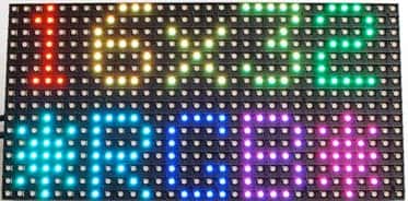
Colorful LED screens are a joy to watch. Bright LEDs making up a 16×32 display are not only easy-to-use, but also low cost – you may have seen such displays in the Times Square. Controlling such a display is simple if you use the low-cost, versatile, credit card sized single board computer, the Raspberry Pi or RBPi. Although the wiring is simple, the display is quite demanding of power when displaying.
The items you need for this project are a 16×32 RGB LED Matrix Panel, Female-to-Female jumper wires, Male-to-Male jumper wires, a 2.1mm to Screw Jack Adapter, an RBPi board and a 5V 2A power supply. Use the Female-to-Female jumper wires to connect the display to the GPIO connector pins of the RBPi. Although this connection is display specific, following a generic pattern is helpful:
GND on display to GND on the RBPi (blue or black)
OE on display to GPIO 2 on the RBPi (brown)
CLK on display to GPIO 3 on the RBPi (orange)
LAT on display to GPIO 4 on the RBPi (yellow)
A on display to GPIO 7 on the RBPi (yellow or white)
B on display to GPIO 8 on the RBPi (yellow or white)
C on display to GPIO 9 on the RBPi (yellow or white)
R1 on display to GPIO 17 on the RBPi (red)
G1 on display to GPIO 18 on the RBPi (green)
B1 on display to GPIO 22 on the RBPi (blue)
R2 on display to GPIO 23 on the RBPi (red)
G2 on display to GPIO 24 on the RBPi (green)
B2 on display to GPIO 25 on the RBPi (blue)
When connecting the wires, ensure that both the display and the RBPi are powered off, as the display is able to pull some power from the GPIO pins. Once all the data pins are connected as above, it is time for the power supply to be connected. The panel has a power supply header and a cable that has two red wires for the positive supply and two black wires for the negative. While connecting these wires to the screw jack adapter, make sure of maintaining proper polarity. Additionally, double check that the power supply you are using is rated for 5V, as any other higher voltage is likely to fry the display. The sequence for powering up must be the display first and the RBPi last.
To display an image or a message, you must convert it to a ppm or portable pixel format. Image editors can do this for you and you can very well use the free open source application GIMP. Once the image is in the required format and placed in the specific directory, the display program picks it up and it appears on the display. Shift registers on the back of the display module help with the shifting or scrolling of the image on the display. Of course, the RBPi has also to do a lot of work in bit-banging the pixels onto the screen.
You may use the code as it is in C, or you may prefer to use Python. Currently, the program displays only eight colors; for reference, see here.