Category Archives: Potentiometers

Basics of Potentiometers

The electronics industry uses many resistance-based components. While in some of them, the resistance is fixed, for others, the user can change the resistance. Potentiometers fall in the second category. Very often, they have a mechanical arrangement that allows the user to change the resistance value manually. Unlike the fixed resistor type components, potentiometers act as variable resistors.

The most common use of a potentiometer is to divide an applied voltage. Therefore, these components serve a dual purpose. On one hand, they help to adjust the voltage output within the circuit, while on the other, they can accurately measure the electric potential. This is the reason for their name being potentiometer. The typical construction of a potentiometer has a resistive element with a wiper. Adjusting the position of the wiper on the resistive element allows the potentiometer to deliver a continuously variable voltage output as a signal on its wiper. It is necessary to add that potentiometers are passive components. That means, unlike active elements, potentiometers do not require additional circuitry or a power supply to operate.

According to physical laws, the resistance of an object depends on many factors, one of them being its length. With all other parameters remaining constant, the resistance of an object will vary directly as its length does. Therefore, two objects made of the same material, with the same cross-sectional area, will exhibit different resistances if their lengths vary. Potentiometers take advantage of this principle to exhibit adjustable output.

The industry uses two types of potentiometers—analog and digital. Our focus is primarily on analog potentiometers, of which there are again two types—linear and rotary. Both rely on mechanical arrangements to manipulate and control the output.

A potentiometer, whether linear or rotary, has a sliding contact that the user can move along a uniformly resistive element. Altering the position of this sliding contact results in its adjustable output. The slider actually modifies the path through which current flows in the potentiometer. With the input voltage applied across the entire length of the resistive element, the output voltage is available as a potential drop between one end of the resistive element and the sliding or rotating contact. By adjusting the position of the moving element along the resistive element, it is possible to determine the voltage applied to the next part of the circuit.

As the name suggests, linear potentiometers employ a straight-line or linear motion using a sliding mechanism for establishing contact with the resistive element. The linear motion adjusts the contact’s position on the resistive element and subsequently, the output voltage.

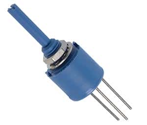
On the other hand, rotary potentiometers use angular movement. They have a shaft connected to a wiper. This wiper slides along a resistive element arranged circularly around the shaft. By turning a knob on the shaft, it is possible to change the position of the wiper, thereby altering the output. Other variants of the rotary potentiometers are also available, where an external tool can rotate the wiper, thereby eliminating the need for a shaft to be present.

How do Electronic Potentiometers work?

Nowadays, most electronic gadgets change their settings such as volume, bass, treble, brightness, contrast, sharpness etc., through “up/down” or “+/-” buttons in contrast to the rotary mechanical controls earlier. These are the electronic or digital potentiometers in action.

While the principle of operation remains the same whether it is a mechanical or an electronic potentiometer, the functionality of the two is quite different. While the mechanical potentiometer offers a continuous variation because it is an analog device, the electronic version is a digital type, offering discrete variations. The difference is due to the way the voltage dividing functionality is implemented in the two versions. As opposed to a single resistance in a mechanical potentiometer, the electronic version has several resistors, also called the resistor ladder network, switched into the circuit with multiple switches.

The voltage at the center terminal of the electronic potentiometer, therefore, depends on the resistance presently connected to the circuit with one of the switches. At first glance, it would seem to be a simple matter to increase the number of resistors and switches to reduce the granularity. However, electronic or digital switching requires each switch to have a unique digital address, usually in the binary format, defined by bits (0 or 1). Higher number of switches means larger number of bits, which increases the complexity of the electronic circuit controlling the switches. The switches, instead of being individual mechanical types, are usually semiconductor types and are integrated into a circuit along with their controller and the resistor ladder network.

This results in a neat little package, which can be soldered in-circuit and requires no panel or knob for its control. Usually, the control is via a micro-controller, which reads the increase or decrease instruction from the UP/DOWN buttons on the remote. It then generates a suitable binary word and sends it to the specific electronic potentiometer chip controlling the volume or any other function you want to change. Depending on the binary word, a specific switch turns on, connecting the required resistance to the central terminal of the potentiometer.

Just like their analog counterpart, electronic or digital potentiometers are also available in a variety of tapers such as linear, log, reverse-log, etc. Taper defines how the wiper voltage changes as it is moved from one end of the potentiometer to the other. For a linear taper potentiometer, both analog and digital, the wiper voltage bears a linear relationship to its physical position. For a potentiometer following the logarithmic or the reverse logarithmic taper law, the wiper voltage is nonlinear.

Since an electronic potentiometer is implemented in a chip, manufacturers adopt different ways of achieving the same results. While resistor ladder network is the most popular, the ladder implementation itself may differ for achieving the desired taper. Some manufacturers use operational amplifiers as buffers before or after the network, some use an anti-thump circuit to reduce the plop noise that is heard when one switch opens and another closes.

One major difference between the analog and the digital versions of potentiometers is the power handling capacity. Typically, the digital versions, in chip form, are unable to handle more than a few mill watts. In comparison, analog potentiometers capable of handling a few watts are quite common.

How Do Mechanical Potentiometers Work?

Electronic gadgets of about one generation back (prior to the prolific use of SMD), used rotary mechanical potentiometers for setting different parameters such as volume, tone, brightness, contrast, etc. For adjusting circuit parameters within the gadget, a smaller variation called the trim pot was a common sight. These are outdated now, but those who still own and use these gadgets often wonder how mechanical potentiometers function.

The most common example of a mechanical potentiometer is the rotary volume (also tone, bass, midrange and treble) control in an audio amplifier. Unless your amplifier has a remote control, chances are that for increasing or decreasing the loudness, you turn a knob labeled as “Volume” control. When you want to reduce the sound output from the speakers, you rotate the knob counterclockwise. The sound output increasing when the knob is turned clockwise. On the remote control, the knob is replaced by two buttons, one marked “+” for increasing and another marked “–“ for decreasing the sound output. Another example is the fan speed control, used mostly prior to the electronic versions.

Therefore, a mechanical potentiometer is a device to control a gadget’s complete range of operation. In its most common use, a potentiometer acts as a voltage divider. This three terminal device has a central pin that allows the resistance to be varied. This is called the wiper – named for the way it makes the mechanical connection to the fixed resistor between the other two terminals. If you connect the wiper electrically to any one of the other terminals, you transform it into a variable resistor or rheostat.

That the device acts like a voltage divider is easily verified from the schematic. If the voltage across the fixed resistor is the difference of voltages Va and Vb, the wiper will show a voltage Vw anywhere between Va and Vb depending on its position. Mathematically, (Va ~ Vb) = (Va~Vw) + (Vw-Vb). The device serves to cancel out tolerances of other components, when used in-circuit as a trim pot; thus allowing the required voltage setting to be achieved.

In construction, a mechanical potentiometer has a fixed resistor in the form of a circular track, stopping just short of a full circle (usually about 270-degrees). The track is printed on a ceramic or a glass-fiber base. The two ends of the resistance form terminals that may either be PCB solderable or suitable for wire termination. Depending on the requirement, the resistance may be of any value between a few ohms to several hundreds of ohms. The entire arrangement is encased in a housing, which also serves to accommodate the wiper assembly.

The wiper assembly consists of a phosphor-bronze spring that lightly bridges the surface of the resistance track and a circular metal track that forms the third terminal. The spring and track arrangement is attached to a metal shaft, but electrically isolated from it. The spring turns as you rotate the shaft, allowing the wiper to change its voltage.

The trim pot has a similar arrangement, lacking only the metal shaft for rotating the wiper. Instead, the phosphor-bronze spring doubles as the shaft, suitable for adjustment with a trimmer screwdriver. Potentiometers may also be of multiple turns to increase their resolution.

How do rotary encoders work?

When tracking the turning of shafts, it is usually necessary to generate digital position and motion information. The most popular way of doing this is by using rotary encoders. They may be incremental or absolute, optical or magnetic, but they are used extensively in industrial and commercial designs in myriad applications. You will find rotary encoders being used on motors paired with automated machinery and drivers for nearly everything from robotics, position control and conveyor speed monitoring on automated industrial machines, elevators and consumer electronics.

Incremental encoders, mostly used for industrial applications, output the shaft’s relative position compared to a reference. In contrast, absolute encoders provide a different binary output for each position that defines a shaft’s position absolutely. Where incremental encoders define resolution as counts per turn, absolute single turn encoders define it as positions per turn, and express it as a multi-bit word. There are multi-turn encoders that track over multiple 360-degree turns and they specify resolution as positions per input-shaft turn along with the number of internal gear ratio turns.

Rotary optical encoders are the most widespread designs used. They typically consist of an LED light source, light detector, a code disk and a signal processor. Although the precision of the mechanical pattern on the code disk defines the measurement precision, there are other factors as well. For example, a quadrature encoder has several opaque regions that produce four distinct reference points. Two of these points correspond to the leading and trailing edges of the region itself. Another two additional points correspond to the leading and trailing edges of a second detector. Apart from providing higher resolution – four times of the code disc – it also indicates direction of turn depending on which detector responds first.

Incremental encoders are named after their outputs, which consist of two square waves, each corresponding to one increment of rotation. A convex lens focuses the light rays from the LED into a parallel beam. This passes through grid diaphragm, whose sole purpose is to produce a second beam of light 90-degrees out of phase to the original. Light from both channel A & B pass through a rotating disc onto the photodiode or photovoltaic array. The rotating disc creates a light & dark pattern as the clear and opaque segments interrupt the beam.

The absolute encoder has a nearly similar structure, except for multiple detectors and multiple unique tracks on the rotating disc. This produces a Gray Code output, which is a binary numeral system where the successive values differ by one bit. One advantage is this information is available even if the encoder has been temporarily shut down.

Although several methods are used to boost the resolution of direct-read encoders, the electric interpolation method is the most widely used. A voltage divider circuit subdivides the raw analog signal into the number of interpolation steps desired. The interpolation is actually a function integrated into the encoder logic and is transparent to the designer. This method allows for boosting the direct-read encoder resolution by about twenty times.

How To Clean Potentiometers On Your Audio Equipment

How to Clean the Potentiometers on Your Audio Equipment

If you have a dirty potentiometer, you probably will find out about it from the scratchy sounds your equipment will make when you adjust the volume control.

Here’s a simple and safe method to rid yourself of that noise:

-Unplug your equipment
-Remove the cover from the knob
-Carefully use contact spray on the shaft of the potentiometer
-Replace the knob
-Plug your equipment back in and turn it on
-Rotate the knob from one end of the range to the other.

Did that work? It should have – but if you still hear the scratchy noise, you can move onto this step:

-After unplugging the equipment again, remove the potentiometer from the housing and use the contact spray at the base. Before you put it back into the housing, rotate the shaft to be sure that it’s moving cleanly.

If you still hear noise, it might be time to replace the potentiometer. Before you cut the wires, it is recommended that you snap a couple of pictures of the previous installation including all wires leading to the potentiometer. This will assist you greatly when it’s time to connect the new pot.

Once you obtain the correct pot to install, you will need to use solder and a soldering gun to reconnect the wire leads from the potentiometer to the equipment.

Hopefully it won’t be necessary to replace the potentiometer. Most often, a spray is all it takes to rid yourself of the noisy potentiometer.

The Basics of Potentiometers

Potentiometer Basics

A potentiometer is a manually variable resistor. It has 3 terminals, one of which is connected to ground, the second to a current source and the third to a sliding contact that runs along a strip of resistor. The varying resistance is used to control other parameter like volume. Potentiometers are widely used electronic components used in volume control, brightness control etc. though recently they are being replaced by digital control circuits.

A potentiometer can regulate the amount of current flow in a circuit. In this case, the maximum current flow is limited by the resistivity of the variable resistor. The variable resistor can be in the form of a linear strip or a circular strip. In a linear potentiometer, the cross section of the resistor is constant and the resistance varies directly with the length of the resistor. In a logarithmic potentiometer, the resistor tapers from one end to the other and the cross section varies likewise. The variation of current flow is logarithmic in this case and is used in audio amplifiers.

A digital potentiometer is digital equivalent of variable resistor potentiometer. It is a digitally controlled electronic component with built in IC or a digital to analog converter. It is widely used in instrumentation amplifiers. It has limitation of being restricted to currents of a few milli amperes and voltage in the 0 to 5V range.