Category Archives: Customer Projects

Customer Project: Dual Power Supply

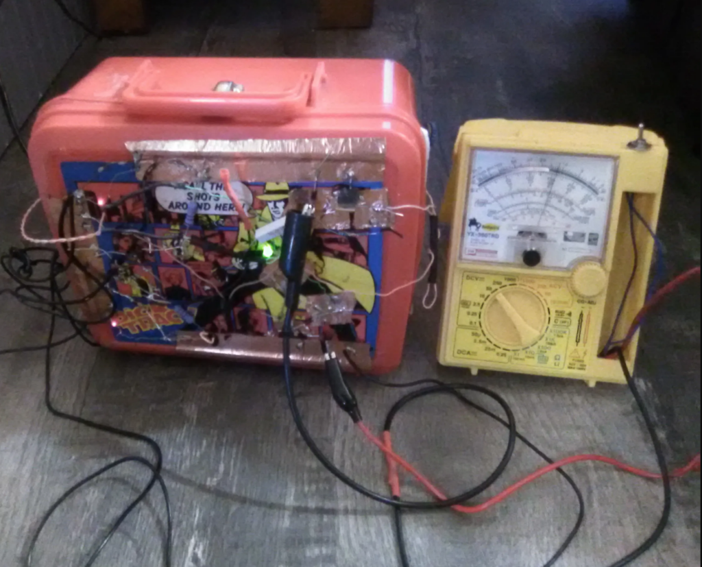
Our customer, Justin, purchased some parts for a dual power supply project and it works great! He said it can output up to +/-30v or 0-60v. It uses two 32vdc printer power supplies instead of a transformer which is inside the case.

See the pictures below of his completed project. Nice job, Justin!

HiFiBerry & Raspberry Pi Put New Life into Old Loudspeakers

If you have some old stereo speakers stored away in your basement, chances are they connect through the old way—with wires—to an amplifier, and that is the reason they were banished to the basement. With HiFiBerry Amp+ and a single board computer, such as the Raspberry Pi (RBPi), you can resurrect your vintage speakers. Using the latest in open source technology, you can now use the renovated loudspeakers wherever you want, since they now operate wirelessly.

HiFiBerry offers their Amp+ as an amplifier for the RBPi. As it is a Class-D power amplifier, it is highly efficient as a stereo module, and you only need to connect the loudspeakers. This high-quality amplifier is ideal for setting up multi-room audio installations.

The amplifier is stable enough to drive 4-Ohm loudspeakers and those with higher impedance as well, pumping out 25 W of output power. However, the best part is the RBPi can fully control the amplifier. As the amplifier includes on-board digital to analog converters, you do not need external sound cards or DACs to provide the 44.1 KHz and 48 KHz sample rates. The board connects directly to the RBPi without needing additional cables, and this provides a full digital sound path for optimal audio performance.

The HiFiBerry Amp+ comes as a pre-fabricated kit, so it needs no soldering. It is a daughter board for the RBPi, and when the RBPi plugs into it, you need to connect only a single external power supply of 12-18 V to supply both the amplifier and the SBC, as the RBPi draws power from the Amp+. You can use the Amp+ with all RBPi models that have the 40-pin GPIO connector. The board sits on four small plastic spacers that come with the kit.

The specialty of the Amp+ kit is it converts the digital signal into audio with far greater clarity than the RBPi can, and delivers that to the speaker as a 25 W audio amplifier. On the reverse side of the board, the female connector is easily visible, so it is easy to plug in the GPIO pins of the RBPi.

On one side of the board are a jack for powering the board, and six wire-terminals. If for some reason you cannot use the jack to power the board, use the two wire-terminals on the left. The rest of the four wire-terminals are for connecting to a pair of stereo loudspeakers, using two audio cables per speaker.

As the board takes in 12-18 V supply and delivers power to the RBPi as well, it is important to not power the RBPi from its usual 5 V power supply. This reduces the number of wires to the assembly. As the Amp+ board is very small, it does not protrude beyond the RBPi. It is important to mount the board on the four plastic spacers to avoid breaking the GPIO pins.

The SD card for the RBPi can be of the 8 GB type and people have reported better performance with Transcend cards. However, you can use 16 GB cards as well.

Do It Yourself Blynk Board

Those who have some experience with Do It Yourself (DIY) electronic projects, and are just starting to test the waters in the Internet of Things (IoT), the Blynk Board from SparkFun is an activity filled challenging exercise. Both experienced users as well as beginners will find this fun to set up and learn—the kit comes with more than ten projects.

Of course, you can make this board work without the IoT Starter Kit from SparkFun, but then you will have to buy the sensors and other components separately to complete the projects. The Blynk Board, based on the ESP8266, runs on a 32-bit L106, a RISC microprocessor core running at a speed of 80 MHz. It has 1 MiB flash built-in, and allows single-chip devices to connect with Wi-Fi, IEEE 802.11 b/g/n. The board has the TR switch integrated, LNA, balun, power amplifier, matching network WPA/WPA2 or WEP authentication, and can connect to open networks. Other features include 16 GPIO pins, I2C, SPI, I2S, UART with dedicated pins, and a UART (transmit-only) capable of being enabled from GPI02. The board also has a 10-bit successive approximation ADC.

Blynk Boards, based on the ESP8266, come preloaded with projects that are ideal for those just beginning on the Internet of Things and concepts of basic electronics. Arduino boards used it originally for implementing Wi-Fi enabled hardware projects; the ESP8266 has built-in Wi-Fi, making it a cheap, Arduino-compatible, and standalone development board. Many other kits use this board in different shapes and sizes, and you will find it in SparkFun ESP8266 Thing, Adafruit HUZZAH, and NodeMcu.

As the ESP8266 is useful as an open source hardware, it is a useful device for starting with the Internet of Things. It makes the Blynk Board an ideal platform for controlling single board computers such as the Raspberry Pi, and Arduino. Basically, the Blynk consists of three components—a Blynk app for smartphones, the Blynk library, and the Blynk server. The library is compatible with a large number of maker hardware.

While the Blynk library and Blynk server are open source, anyone can use the Blynk app on iOS and Android smartphones. With the Blynk app, you can build a graphical interface for any IoT project—simply drag and drop the widgets. Blynk offers several widgets such as LC display, buttons, and joystick, with which you can start hacking and you need only an IoT development board.

After collaborating with SparkFun, Blynk created the ESP8266 based SparkFun Blynk Board. They offer it fully programmed for more than ten Blynk projects. That makes the IoT Starter Kit from SparkFun with the Blynk Board such a fun project, offering a wonderful introduction to the Internet of Things technology and you do not have to learn any difficult programming.

For those who already have other ESP8266 development boards, simply reprogramming them with the firmware will turn them into DIY Blink Boards. With these, you can easily run boot camps or conduct workshops. Just adding the sensors and a few other components will help you complete the built-in projects, and these you can buy from SparkFun.

Which are Better – Round Cables or Flat Cables?

Both types of cables are available in the market—round ones and flats, and people use them according to the requirements of the application. As round cables were the first to arrive on the market, the industry has been using them as standard for long, in applications ranging from renewable energy to automation and manufacturing in general.

Flat cables arrived late on the scene, and offer a niche solution presently. However, they are gaining ground steadily for applications within the civil-aircraft markets, semiconductor industry, medical field, and for supplying data and power to machines. Flat cables are also called festoon cables, and the overhead crane companies actively use them for applications where winding cables around spools is difficult.

Comparison of Electrical Performance

The protection for internal EMI depends heavily on the construction of the cable. In general, flat cables do not transfer data very well. Individual shielded pairs within flat cables are necessary to provide coupling and crosstalk protection from pair to pair.

Most shielding materials to not hold a flat format and tends to become round. This makes it difficult to place a shield on the flat cable overall. This also makes it difficult to protect and shield a flat cable from the effects of external EMI. The naturally round shielding tendency provides greater protection against influences of external EMI on round cables.

The length of a cable, its quality of insulation, and the resistance of its conductors determines the voltage drop or attenuation on a power cable and this is immaterial whether the cable is round or flat. In both cases, higher quality of insulation and proper positioning of the ground wire improves the attenuation. Certain industries demand very high-performance (low attenuation and crosstalk) flat cables. With proper shielding, it is possible to transmit both power and signals through the same cable.

Comparison of Mechanical Performance

Cables in the industry face mechanical stresses of four main types—S-bend, rolling flex, tic-toc, and torsion. The natural capability of being able to move in multiple axes at the same time makes round cables capable of withstanding all the stresses. For instance, round cables can flex 30 million times in certain applications. On the other hand, flat cables can withstand only rolling flex, as the movement is only in one linear axis.

Movements in several axes such as during torsion can lead to flat cables binding, or twisting beyond a certain point. When under torsional loads, flat cables can spool and twist over a certain length. Preventing this requires every component of a flat cable to be integrated at the right position and twist. It also requires the cable to be embedded or wrapped with a PTFE (Teflon) tape for minimizing the frictional forces during torsion.

Summary

Round cables can maximally utilize the space inside the smallest required cross-sectional area. Drilling a round hole is easier than cutting a rectangle. Therefore, most machine or panel openings use round cables where using a flat cable may be more difficult, as it has an elongated cross-section. However, it is possible to stack flat cables to make them fit together in a smaller space than it is with round cables.

Raspberry Pi Controls the Cardboard Dog

This is a project for beginners using the Raspberry Pi (RBPi) single board computer. The RBPi is used to control a servo for turning the head of a cardboard dog away whenever a person is looking at it. This is to mimic a begging dog that seems ashamed of its begging nature.

This project requires the SBC RBPi, its power supply with the 5 V micro-USB cable, a USB keyboard and mouse, a display, and an HDMI cable. For storing the OS, an 8 GB micro SD card is also necessary. Another computer will be necessary to write the OS to the micro SD card and edit the files in it. The official PI camera will help to recognize the faces looking at the dog, and a micro servomotor is required to turning the head.

The RBPi will be controlling the servo through its GPIO pins. The servo has three wires that need to connect to the GPIO pins using female connectors. The camera has a ribbon cable, which goes into the port labeled camera on the RBPi. The HDMI cable goes into its port on the outside of the RBPi, and its other end goes to the HDMI-compatible TV or monitor.

Download and install the latest version of the Raspbian (with Pixel) from the official website of the RBPi. While installing the image on to the micro SD card, the process will destroy all data on the card, so be sure there is nothing of value before you begin.

Once the OS is installed on the micro SD card, insert it into the slot on the reverse side of the RBPi. If the power cord is now plugged into the RBPI socket and the power turned on, there should be some code running on the monitor screen, with the desktop showing up at the end. At this time, right click anywhere on the desktop and select “Create a New File.” Name the file Dog Turn.py, and select it to open with Python 2 IDLE.  Now open IDLE, and paste the code from here into it.

To make the code in the file to work, the RBPi will need additional Python modules to be installed. These are the libopencv-dev, python-opencv, python-dev, and you must use the sudo apt-get install command to download them.

The cardboard dog for this project uses four 9×6 inch cardboard rectangles, and two 6×6 inch squares, which form the main body. A hole at the top of the box allows the servo to go through. Another 5-inch cardboard cube forms the head, and attaches to the servo. Some cardboard legs make the dog look more realistic.

The entire electronic hardware can fit within the body of the dog. It may be necessary to use standoffs to hold the RBPi in place. The camera should look out from one of the eyeholes in the dog head. Fix it in place so that the cable has sufficient play when the servo moves the head. Simply running the python code should be enough to let the dog do its trick. To stop, turn off the power.

Voice HAT for Raspberry Pi for Controlling a Motor

If you were one of the unlucky ones to miss out on the issue 57 of the MagPi, then the only option is to buy the Voice HAT from the AIY projects. The issue 57 had offered a free AIY projects Voice Kit, which Google had developed to make a Voice Assistant, and you could control a speaker with the voice HAT that attached on top of a Raspberry Pi Zero (RBPiZ).

Other tutorials in the MagPi show how to connect the Voice HAT hardware to simple circuits.  So far, the tutorials have dealt with LED lights and servomotors, but this project is somewhat more complex—using the Voice HAT to control a DC motor. Therefore, you will need a DC motor, four AA size batteries, breadboard, and jumper wires.

Usually, the RBPiZ draws its power from the power supply on the Voice HAT board. For this project, this connection has to be broken, else the motor may draw too much power from the RBPiZ and short it. On the Voice HAT board, locate the external power jumper marked JP1, and use a sharp knife to cut the track. If you later wish the power to be shared again between the board and the RBPiZ, re-solder the cut joint.

Power off the RBPiZ and the Voice HAT, and connect the positive terminal of the DC motor to Driver 0, middle pin, which is marked with a “+” symbol. Same way, the negative terminal of the DC motor connects to the “–“ pin of the Driver 0. As this pin connects to the GPIO4 pin, it allows the motor to be turned on and off.

The four AA battery pack connects to the +V and GND pins on the Voice HAT. This ensures the motor is supplied adequate power from the battery pack and the Voice HAT and does not crash the RBPiZ when it draws power. Now turn on the power to the Voice HAT, and then turn on the battery pack.

At this point, you are ready to turn on power to the RBPiZ. Boot into the AIY Projects software and enter the code from motor.py for testing the circuit. The control to the motor comes from the PWMOutputDevice from GPIO Zero, and this allows managing the speed of the motor.

The motor is controlled via a Pulse Width Modulation (PWM) method. The RBPiZ controls the power to the motor by controlling the on and off periods. If the on period is more than the off period, the motor receives more power and therefore, rotates faster.

To manage the speed of the motor, you control the variables .on() and .off() in the software.  Alternately, you may set the value of the instance variable to a value between 0.0 and 1.0 for controlling the speed. Here, 0.0 means the motor is a dead stop, while 1.0 sets the motor to a maximum speed. The motor.py uses both techniques and you can also use pwm.pulse() for pulsing the motor on or off. To integrate this with the Voice Assistant, enter the code from add_to_action.py to the relevant sections. You can now control the motor using voice commands.

A Music Server on Your Raspberry Pi

If you are looking to create a music server on your Raspberry Pi (RBPi), Volumio may be a suitable choice. Although several websites give perfect instructions for setting up the RBPi as a media center for watching films and video series, very few provide solutions for audiophiles who would prefer to have a server dedicated to music.

Volumio is available as a Raspbian distribution. Using the application, one can manage the entire music library on a single device attached to the RBPi. Being very easy to use, Volumio supports all types of audio files—Vorbis, AAC, FLAC, mp3, and more. It even works with several DAC expansion cards. The team behind Volumio maintains it providing updates at least once a month, and this shows their seriousness in supporting this wonderful product.

The best way to get Volumio is to download it from their website. It is available as a Raspbian image, and it is necessary to download the image and decompress it. You will need a micro SD card to flash the uncompressed image—use one with a 16 GB capacity. Flashing requires a PC running Linux, Windows, or MAC. There is no need for an Ethernet cable, as Volumio works with a Wi-Fi connection.

It is advisable to use an RBPi3 with Volumio. On the first run, Volumio proceeds to install the application, which can take up quite a few minutes. In the selection presented, choose Wi-Fi and Volumio will try to connect with a network. If it does not find any network, or the network is inaccessible, Volumio will proceed to create its own hotspot. You can access this hotspot from your PC with the name Volumio and password volumio2. Typing the IP of your RBPi3 or the address volumio.local/ will take you to its web interface.

Once you are able to connect to Volumio on your PC, visit the Network tab, and move to the Wi-Fi Network section, where you can enter the code of security. Now you are fully equipped to run Volumio on your RBPi3, and add all your songs.

This is again a very simple process, and the recommendation is to have an external hard drive for this. Simply store all your songs on the external hard drive and let the RBPi3 use it. Navigate to Browse, then to Music Library, and select USB, which will allow you to see the hard drive. Alternatively, access the contents of the hard drive directly from the Album or Artist sections. Another possibility is to use a Network Attached System (NAS). For this, you must access the section My Music.

Still another possibility is to play the titles of Spotify, and you can do this by adding a plugin. This requires you to navigate to the Plugins section, and installing it from there. Once the installation finishes, activate Spotify on the RBPi.

Volumio is compatible to DLNA and AirPlay. Therefore, it is possible to broadcast audio streams from an iPhone. As Volumio offers a digital output, adding a DAC expansion card to the Raspberry Pi brings further gain in quality and listening pleasure.

Your Own Home Assistant with the Raspberry Pi

In the past one year, several off-the-shelf home assistants have made their way to the market. Some of the most famous of them are Siri, Google Home, and Amazon Alexa. For people too lazy to move, it is a pleasure to simply announce, “…, resume my audiobook“ or, “…, turn off the bathroom light,” and let the assistant do their bidding. In this melee of big names, there are several home-brew variants as well, some of them built on to single board computers such as the Raspberry Pi (RBPi). Many use them simply to have the time announced to them, along with allowing them to perform home automation tasks.

Therefore, if you are interested in making your own home assistant run on your RBPi, try the Gladys project. According to the website of the creator, the Gladys Project is an open-source program running on the RBPi and capable of connecting with all devices and checking the calendar to help with everyday life.

Apart from the basic day-to-day maintenance tasks that are necessary in life, Gladys can wake you up in time for work, if you have missed your regular alarm clock. Not only that, it can also play the video you ask it to play.

For instance, Gladys will gladly help in directing you to your work, taking into condition road conditions and travel time, ensuring you are never late, regardless of external factors. If there is a road blockage, say because of a queue on the motorway, which may make you late for work by about half an hour, Gladys will wake you up half an hour early. Also, while you shower and dress for work, Gladys opens the blinds and starts to brew coffee. If you are working around the house, Gladys will read and audiobook aloud, and you can request her to pause while you turn the mixer on.

Gladys detects your return home at the end of the day, and runs the evening routine you have set. As soon as you set your phone on the NFC tag to indicate bedtime, Gladys turns off the lights, and if programmed for it, starts the music playing, sending you into a deep slumber.

You can download Gladys as a pre-built Raspbian image. It is a free download from the website of the Gladys Project. Gladys is compatible with smart devices such as WeMo Insight Switches, Philips Hue light bulbs, and even the Sonos speakers, notorious for being difficult to control without their official app.

The download is in the form of a zip file. Unzip it to get the image file. Now, clone this image on to SD card you want to use with your RBPi. For this, use the program Etcher, which works on all operating systems including Linux, Windows, and Mac.

Connect the RBPi to your local network with an Ethernet cable or Wi-Fi and turn it on. At this point, it is a good idea to expand the partition on the SD card, to allow the system access to the full size of your card; else, it may run out of disk space very soon.
Industrializing your Raspberry Pi

You can turn your Raspberry Pi (RBPi) into a completed computer system with the minimal effort. Using a pre-assembled, cost-effective kit will not only save you a lot of time, but also speed up the installation and slash development time as well, allowing you to realize the full potential of your single board computer. This industrialization of your SBC brings huge commercial potential and encompasses a wide range of applications, including using the system for payment terminals, communication systems, IoT products, home technology, medical devices, machine tool control systems, industrial automation, and more.

The PCAP 10.1-inch Touch Screen Kit from Inelco Hunter is specially designed to work with the popular single board computer, the RBPi. You can buy the kit in pre-assembled form and simply mount the RBPi onto the interface PCB on its rear, fixing it in place using the supplied pillars and screws. You can then mount the display as a panel or flush mount it to get resolutions up to WXGA.

Customers looking for a larger screen format for the RBPi can now upgrade from the earlier 7-inch display format from the same designer, Anelco Hunter. He developed this new screen for customers looking for extra screen space. Using the kit, customers can industrialize their equipment quickly and easily by providing it with a larger screen. No further upgradation is necessary, as the same programs and software already available for the 7-ich version will continue to be useful.

According to the Managing Director of Inelco Hunter, David Bushnell, the idea for a bigger screen format for the RBPi was born after a number of customer requests were made following the launch of their 7-inch kit. The kit maintains the same quality of the 7-inch model’s TFT screen with industrial grade while transitioning to the bigger screen format, maintaining the earlier high-quality metrics and ongoing availability.

A PCB provides the connections on-board for HDMI interface, along with the required conversions for signal, power, and backlight required by the TFT display. To drive the TFT display, the user has to supply it with 12 V at 2 A. This is apart from the 5 V at 2 A the RBPi requires for operating.

The PCAP touchscreen offers features such as pinch, zoom, and rotate through either USB or I2C connection. While the screen dimensions are 255 x 174 x 9 mm, the view area is 218 x 137 mm. The wide-angle IPS display offers a resolution of 1280 x 800 pixels.

Inelco Hunter has designed their display kit to work with all models of the RBPi family. They have tested the kit to operate at temperatures of +70°C and this underlines its reliability. This further supports the mean time before failure (MTBF) figure of 50,000+ hours. All these specifications make this display a good choice for those looking for a design with a long life and reliability.

Customers buying the kit will find a 10.1-inch Touch Screen TFT display, a pre-assembled interface PCB for HDMI to LVDS conversion, a connector for HDMI to HDMI interface, a micro USB to USB cable interface, and the pillars and screws for mounting the RBPi.

Let Raspberry Pi Automate those Snake Eyes

If you are looking for something to bring your cosplay masks, props, or other spooky sculptures to life for your robots, animatronics, or Halloween parties, you can use the snake eyes cowl as a pair of animated eyes. This is an accessory for operating two 128×128 pixel TFT LCD or OLED displays through a single board computer such as the Raspberry Pi (RBPi). It also has four analog sensor inputs.

The project started life as a project named Electronic Animated Eyes using the microcontroller Teensy 3.2. However, the author found the RBPi to be a better alternative as it offers some potential benefits, such as hardware-accelerated graphics, and includes antialiasing. With a faster CPU, dual SPI buses, and ample RAM, the RBPi offers faster frame rates. The RBPi does not require a preprocessing step to decode standard graphics formats such as SVG, PNG, and JPEG. The author has written the eye rendering code in a high-level language, Python, and that makes it easier to customize.

However, using RBPi for this project has some downsides as well. The RBPi usually takes a while to boot an operating system from an SD card. It also needs an explicit shutdown procedure. As the RBPi is large and uses more power, it is not very suitable for wearable applications. Moreover, the use of an SD card makes it less rugged.

The author recommends an RBPi model 2 or 3. Although the code runs fine on an RBPi Zero or another single-core RBPi board the performance will lag greatly. Make sure the RBPi board used for the project has a 40-oin GPIO header.

However, it is not necessary to connect both displays for the project, as a single eye can also produce a very creative effect. The author recommends OLED displays, as they have very wide viewing angle along with excellent contrast and color saturation. However, OLED is more expensive compared to TFT. TFTs are also acceptable as displays, although they may look somewhat washed out for this project. Users may need additional components if they plan on controlling the eyes with a joystick and buttons, and allowing them to react to light, rather than allowing them to run autonomously.

The author uses bonnet boards to wire up the breakout pins on each display board. The user must decide if the installation will be a temporary arrangement or a permanent one. Space for wiring may depend on the housing chosen for the installation, and these may influence the choice of connectors and wiring. Wiring has to be done carefully, following the instructions to avoid disappointment.

Preferably, solder a header at each end, and plug all the wires through. This is easier and less error-prone. Keeping the wiring short and tidy from the bonnet to display, ensures the display gets a clean signal, as electrical interference may lead to glitches in the animation.

Start the project by downloading the latest version of the Raspbian Lite operating system, and transfer it to an SD card of 2 Gb or larger size. Follow instructions here.