Category Archives: Relays

Difference Between Protection and Control Relays

Today’s industrial revolution is paced fast enough to require the safety of people and processes through protection systems. There are many types of electronic protection relays, and they are different from standard control relays. Being an essential element of industrial control engineering, it is impossible to conceive of machine control without relays. Traditionally, almost all relays have ON/OFF features. However, relay technology has advanced, and now protection relays can have more than the customary features.

For instance, protective relays can measure specific process variables like voltage and current and switch the output based on the measured values. On the other hand, control relays do not monitor anything. Rather, by detecting the presence of an electrical signal at their input terminal, they change their output contact state.

For integrating into a machine, it is necessary to specially wire protective relays. Control relays, being simple, do not require complex wiring.

In an industrial scenario, the main objective of protective relays is to prevent electrical and electronic systems from exposing any type of hazards. Control relays can only switch applications, like switching from one state to another, but they do not inherently protect from hazards.

Some protective relays can indicate the value of the variables they measure, such as current or voltage. However, control relays cannot do anything like that, only outputting the state change.

Many types of protective relays are available on the market. Their selection depends on the nature of the hazard from which the protection is desired.

For instance, an earth fault relay offers protection in a system where current is passing through an earth terminal. In a system, current passing through an earth terminal represents a significant fault in the wiring. It can damage not only the wiring but also the connected electronic and electrical components. The earth fault relay recognizes the current flowing through the earth terminal and protects the system from this hazard.

When the earth fault relay detects current flow through the earth terminal, it trips the connected circuit and sounds an alarm to protect the system from the hazard. To detect the current, it uses a current transformer connected to the earth terminal.

For instance, moisture can short the phase terminal to the earth terminal. This causes current to flow from the phase terminal to the earth terminal, creating an earth fault. On detecting such a current flow, the earth fault relay typically trips the circuit breaker, cutting off supply to the connected circuit. Simultaneously, the relay indicates the fault with the alarm flag. Medium to high-voltage applications typically use earth fault relays. These include substations, transformers, and distribution panels.

Voltage relays protect the system against voltage fluctuations. Two major voltage relay types are undervoltage and overvoltage relays. While overvoltage relays protect the connected system from voltage supply greater than a certain level, an undervoltage relay protects the system from voltage drops below a certain level.

This is necessary to protect equipment from the hazards of voltage supplies below and beyond the specified level damaging electronic and electrical components. Voltage relays are available for AC and DC systems, and voltage values range from 5 to 500 V.

Understanding Signal Relays

For upwards of 180 years, the relay has been one of the most valuable devices in the electrical and electronic industry. Their major function is remote control of a circuit from a distance, and this makes them significantly useful in a wide variety of applications. For instance, early computers had innumerable relays to conduct Boolean logic functions. A signal relay is a major subcategory of relays, with a specific and important function in the communications industry.

Like regular relays, signal relays are also electrically operated electromechanical switches. Their function is typically to control the current flow in a circuit. A control current flowing through a coil near the contacts generates a magnetic force, and this moves internal parts to open or close the contacts controlling a secondary circuit. This allows a small current in the coil to control a larger current in the secondary circuit.

Although the above functions are similar to those of a power relay, the design of a signal relay makes it more suitable for handling low currents and voltages, typically lower than 2 A, and voltage ratings between 5-30 VDC. The design of their contacts is suitable for handling low power.

Coming in small packages, signal relays are eminently suitable for mounting on PCBs or printed circuit boards. As their mechanical design makes them light, they offer significantly faster switching times as compared to power relays. Signal relays are far less expensive than solid-state relays and are impervious to voltage and current transients. They are also not susceptible to EMI or RFI. Since they are small and handle low power, they generate significantly lower amounts of heat than solid-state relays do, thereby requiring very few thermal management solutions in the PCB.

Like other electromechanical relays, signal relays also offer several benefits. These include simple design, robust operation, electrical isolation, cost savings, multiple feature options, and immunity to EMI and RFI. With a proper matching to meet the power requirements of the circuit, signal relays can offer additional benefits. These include affordable cost, small size, ease of use and operation, ability to withstand mechanical shock and vibrations, and high insulation between primary and secondary circuits.

For selecting a signal relay for a specific circuit, the designer must consider multiple factors. These include the maximum voltage that the relay must switch, the maximum current that the relay must switch, the contact resistance, the relay coil voltage, the relay coil current, the contact form, switching time, mounting type, operating temperature, and dielectric strength.

The above list is the minimum requirement for an engineer to start choosing a signal relay for their project. For instance, they can determine the necessary secondary voltage and current ratings from the maximum load that the circuit must switch. For a signal relay, it is essential that it switches a current lower than 2 A. Next, they must identify the number of circuits the relay must switch. That is, the number of poles on the relay contacts, and whether the arrangement should be normally closed or open. The next point to identify is the primary or control voltage that operates the relay, and whether this is AC or DC.

What are MOSFET Relays

For certain applications, especially for high-power switching, traditional electromagnetic relays are still a popular choice. However, with the advent of solid-state relays, particularly MOSFET Relays, this trend is now shifting for a growing range of applications. In addition, with IoT growing exponentially, and 5G networks moving the trend towards shrinking form factors, engineers are forced to fit more powerful devices with higher functionality into smaller spaces. That means, they must also find better ways of improving power efficiencies through improved switching speeds.

Modern IT infrastructure, such as switching power supplies and DC-DC converters, presents engineers with specific design challenges. MOSFET relays help to address these challenges as their characteristics are superbly suited to several key applications.

Although the name includes the word relays, MOSFET relays are actually electronic circuits rather than relays and feature an input and an output side. The input side comprises a PDA or photodiode dome array, along with an LED or Light Emitting Diode. The output side comprises a FET or Field Effect Transistor block, with a control circuit bridging the two.

To activate a MOSFET relay, a current must flow through its input LED and turn it on. The PDA then converts the light from the LED to a voltage. The control circuit uses this voltage to drive the output block. This action turns on the double MOSFETs, present in the output block, allowing them to pass either AC or DC loads bi-directionally.

Unlike electromagnetic relays, MOSFET relays have no moving parts. Therefore, the latter can withstand vibration and physical shock without suffering damage or malfunction. Ideally, the MOSFET relay should perform indefinitely, operate silently, and cause very little electrical interference, provided it is under proper use.

While MOSFET relays can handle a wide range of input voltages, they consume very little power and do not arc during operation. That makes this solid state relays eminently suitable for working in hazardous environments. While enabling the switching of both AC and DC signals, solid state relays minimize surge currents. A physical comparison with electromagnetic relays reveals MOSFET relays to be considerably smaller, occupying less space on printed circuit boards, and consuming very low power.

Certain characteristics of MOSFET relays offer advantageous implications in electronic applications. For instance, they offer low output capacitance, implying an improvement in switching times with better isolation characteristics for load signals at high frequencies. The presence of an LED at the input implies optical isolation between the input and output circuits offering a better physical or galvanic isolation. The on-resistance for MOSFETs is low, implying increased switching speeds and low power dissipation when switching high currents. Being solid state, MOSFET relays have no hysteresis when switching from the on-state to the off-state and vice versa. These relays have high linearity, ensuring there is no signal distortion when switching. Therefore, MOSFET relays are equally suitable for analog and low-level signal switching.

The above characteristics of the MOSFET relay make them ideally suitable for a wide range of applications. These include use in energy-related equipment, telecommunications, factory automation, amusement equipment, security equipment, medical equipment, automated test equipment, and much more.

Three-Phase Monitor Relays Protect Expensive Machinery

Three-phase motors power many industrial and commercial machines. One can find these machines in material handling, water treatment, air conditioning systems, ventilation, heating, marine, machine tools, and aviation applications. However, a range of fault conditions can damage these reliable devices when not addressed quickly. This can lead to a shortened operating lifetime or even a failure, resulting in significant repair costs and downtime.

Phase monitoring relays can detect these faults, notify the operators, and stop the machinery before it develops permanent damage. These relays detect the presence of all three phases, their correct sequence, and that all phase voltages are within the specified range. Should an error develop, the relay opens a set of contacts, initiating an alarm condition, and powers down the machine. There are many types of phase-sensing relays. They can handle a wide range of phase configurations, voltages, and errors.

Among the common failure modes of three-phase motors, are those related to their three-phase power source and their effects on the motor. An imbalance in the phase voltages, or a loss in one of the three phases, can result in the remaining phases driving higher-than-normal currents into the motor. This can lead to a loss of rotational power and excessive vibrations. Likewise, over-voltages and under-voltages can force the motor to draw excess current for driving the same load, and this can shorten the life of the motor. An incorrect phase sequence may cause the motor to reverse the direction of rotation. This can have significantly disastrous results on the load connected to the motor.

Phase monitoring relays monitor the state of the three-phase power source. The three-phase lines that they monitor also power them. Apart from the phase sequence, they also monitor the loss of any phase voltage. Only when all the phases are present, and are in the correct sequence, do the relays activate. Whenever there is a loss of any phase, or the phase sequence is incorrect, the relays de-energize.

Some phase monitoring relays also have the capability to monitor the voltage levels of all three phases. This typically uses a true root-mean-square measurement. The relay deactivates whenever the voltage drops below a preset threshold. Some relays also offer adjustable limit settings along with voltage detection. Other relays monitor phase asymmetry along with tolerance. Typically, phase monitoring relays offer a delay before actuation. This prevents spurious activation from temporary voltage levels or asymmetry issues. In some models, the delay is adjustable.

The DPA01CM44 is an example of a three-phase monitoring relay meant for three-wire configurations. The three-phase source powers the relay. Relay models available operate at voltages of 208, 230, 400, 600, and 690 VAC. Although relays for mounting on DIN rails are typical, plugin models are also available. The relay output configuration can be single or dual SPDT contacts.

Normal voltage and phase conditions allow the relay to remain activated. That means, the normally open contacts of the relay output remain closed. Abnormal conditions make the relay operate within 100 milliseconds. The front panel on the relay has status LEDs to indicate relay activation and power on.

What is Industrial Connectivity?

Engineers include any component involved in the path of delivering control signals or power for doing useful work as part of industrial connectivity. Typically, components such as terminal blocks, connectors, motor starters, and relays are part of industrial connectivity.

Engineers divide industrial connectors into four categories depending on the environments in which they operate—commercial, industrial, military, and hermetic. Commercial applications do not consider temperature and atmosphere as critical operating factors affecting performance. Industrial applications require connectors capable of handling more rugged environments involving hazards such as sand, dust, physical jarring, vibration, corrosion, and thermal shock.

Most general connectors use low-cost materials to merely maintain electrical continuity. However, designers have a large variety of materials from which to choose for making connectors. These include brass, beryllium copper, nickel-silver alloys, gold, gold-over-silver, gold-over-nickel, silver, nickel, rhodium, rhodium-over-nickel, and tin.

No wire preparation is necessary for use in terminal blocks. The user only needs to strip the insulation and install the wire using a screwdriver. One can use a wide range of wire sizes with terminals that provide an easy way to hookup wires from different components, ensuring fast connection/disconnection during troubleshooting and maintenance.

Manufacturers make terminal bodies from a copper alloy with the same expansion coefficient as the wire it connects. This prevents uneven expansion from causing loosening between the connector screws and the wire, avoiding an increase in contact resistance. Using similar metals also avoids corrosion, usually with two different metals in contact, as a result of electrolytic action between them.

SSRs or Solid-State Relays control load currents passing through them. For this, they use power transistors, SCRs, or silicon-controlled rectifiers, or TRIACs as switching devices. Engineers use isolation mechanisms such as optoisolators, reed-relays, and transformers for coupling input signals to the switching devices to control them.

To reduce the voltage transients and spikes that load-current interruptions typically generate, engineers use zero-crossing detectors and snubber circuits, incorporating them within solid-state relays.

Semiconductor switches generate significant amounts of waste power, and engineers must minimize their operating temperature using heat sinks attached to solid-state relays. SSRs can operate in rapid on/off cycles that would wear out conventional electromechanical relays quickly.

Electromechanical relays physically open and close electrical contacts for operating other devices. In general, they cost much less than equivalent electronic switches. They also have some inherent advantages over solid-state devices. For instance, the input circuit in electromechanical relays is electrically isolated from the output circuits, and one relay can have more than one output circuit, each electrically isolated from the others.

Furthermore, the contact resistance offered by electromechanical relays is substantially lower than that offered by a solid-state relay of a similar rating. The contact capacitance is lower as well, benefitting high-frequency circuits. Compared to solid-state relays, electromechanical relays are far less sensitive to transients and spikes, not turning on as frequently as SSRs do. Brief shorts and overloads also damage electromechanical relays to a far less extent than the damage they cause to SSRs.

Improved manufacturing technology is now making available electromechanical relays in small packages suitable automated soldering for PCB mounting and surface mounting.

Using Relays to Detect Faults

Different types of relays are in use in every-day life. These include relays constructed from electromechanical elements such as from solenoids, induction discs, hinged armatures, or from solid-state elements such as from transistors, magnetic or operational amplifiers, silicon-controlled-rectifiers (SCRs), diodes, or digital computers using microprocessors and analog-to-digital converters.

Development of protection with relays began with the electromagnetic types, and most descriptions of relay characteristics still retain the electromagnetic terms. Although the construction of a relay does not inherently alter the concept of protection, each type has its own advantages and disadvantages.

General faults are often short circuits, where the current increases in magnitude, while the voltage goes down. Apart from the changes in magnitude, the AC field may also undergo changes in parameters such as system frequency, active/reactive power, harmonic components, phase angles of the current and voltage phasor, and more.

Operating principles of detection of faults with relays are based on detecting the above changes and identifying whether the changes exist within the predefined zone of protection or outside. Depending upon the operating principle of the relay, detection can be categorized based on which of the input quantities the specific relay will respond. This leads to eight major types of faults that relays can detect:

  • Frequency Sensing
  • Harmonic Content
  • Pilot Relaying
  • Distance Measurement
  • Phase Angle Comparison
  • Differential Comparison
  • Magnitude Comparison
  • Level Detection

Most power systems operate at a normal frequency of 50 or 60 Hz, depending on the country. Deviating from the normal frequency indicates an existing problem or an imminent one. Engineers use frequency-sensing relays to detect and take corrective action to bring the system frequency back to normal.

Power systems usually operate with a sinusoidal waveform of the fundamental frequency. Abnormal system conditions create harmonics that are typically associated with heat and loss in efficiency. Electromechanical or solid-state relays can detect these harmonics, based on which control action may be required.

Sometimes information is required from a remote location, and a pilot relay provides it in the form of contact status, open or closed. Usually, this information is carried over a channel of communication using telephone, microwave, or carrier circuits.

An impedance relay determines the distance or length of the line based on a given spacing and diameter of the conductor. The relay compares the local voltage with the local current, and gives a measurement of the line impedance as seen from its terminals.

A phase angle comparison relay compares the relative angle of phase between the AC voltage and the AC current, measuring the power factor angle. This comparison determines the direction of flow of the current with respect to the voltage, with the magnitude of the angle measured giving an indication of faults.

Under normal operating conditions, current entering one end of an electrical equipment should equal the current exiting from the other end. However, in case of any fault within the equipment, this balance is no longer maintained. A differential relay detects the difference in the two currents, and provides protection.

Relays can compare the magnitude of current in one circuit with the magnitude of current in another and detect abnormalities based on whether they should have been equal or proportional.

Finally, relays can be designed to trip the circuit breakers should the operating current level crosses a specific setting.

RS485 Relay Output Module for the Raspberry Pi

Although many consider the RS485 relay output module as an archaic protocol, it is still important to the industry. The RS485 protocol allows up to 32 devices to communicate through the same data line over a cable length of up to 4000 feet with a maximum data rate of 10 Mbps. Not many other protocols can equal those numbers.

The single board computer, the Raspberry Pi (RBPi) is increasingly finding its way into more and more industrial applications. However, the limiting factor for most compatible relay modules is the number of contacts available, which are either too few, or limited by the GPIO pins used.

The RS485 relay interface overcomes this limiting factor. Modules such as the Pi-SPi-RS485 and VP-EC-8K0 support the Modbus protocol. That offers the industrial user up to 253 modules at eight relays per module, theoretically making it possible to use 2,024 relays from one interface. Practically, there are two limitations.

According to the hardware protocol, the RS485 relay can support up to 32 unit loads, before a repeater/amplifier becomes necessary for the next batch of loads. Popular modules use the Texas Instruments RS485 drivers such as the SN65HVD72DR half-duplex IC, which according to the TI data sheet, allow only up to 200 unit loads.

In addition, the hardware protocol of the RS485 relay output module specifies the maximum distance between the extreme ends of the RS485 transmission line cannot exceed 4000 feet. For greater distances, a repeater/amplifier becomes necessary.

Therefore, for any industrial application requiring serious outputs such as few hundreds of easily configurable relays, each with 10 A SPDT contacts with MOV protection, where the distances are within 4000 feet between all modules, the RS485 modules for the RBPi are a perfect fit. Some modules are field ready as they have an optional DIN rail enclosure.

RS485

RS485 is an industrial standard for transmitting serial data via a hard-wired cable—EIA/TIA-485 defines the system. RS485 offers the ability of multi-drop cabling with data speeds of up to 10 Mbps over 50 feet, and slower communication speeds of 100 kbps for up to 4000 feet. Industrial applications such as data acquisition widely use the RS485 protocol.

Simple networks often use RS485 links, connected in 2- or 4-wire mode. A typical application may have several addressable devices linked to a single controller, PC, or SBC such as the RBPi. This typically uses a single line for communication.

Using simple interface converters, linking systems using the RS485 and RS232 protocols is possible. This may include optical isolation between the two circuits. It is also possible to incorporate surge suppression for any electrical spikes that the communication line may pick up.

RS485 makes it easy to construct a multi-point data network for communication. According to the protocol, you can have 32 nodes capable of both transmitting and receiving. Furthermore, you can easily extend this capability further by using automatic repeaters and using high-impedance drivers/receivers. That means hundreds of nodes can exist on a network, extending the common mode range for both drivers and receivers with tri-state and power off modes for power saving.

What are Optically Isolated Relays?

Popularly, relays are known to be electromechanical devices. However, engineers today have access to solid-state relays that operate without any electromagnetic or moving parts. Where reliability and performance is paramount, engineers prefer to use solid-state relays to their electromagnetic versions. However, solid-state relays are more expensive.

While traditional relays have several mechanical failure modes associated with moving parts, solid-state relays offer several advantages in performance and design. These include low power consumption, low leakage current, stable on-resistance, high reliability, extremely long life, small size, fast switching speeds, high vibration and shock resistance, and no switching noise from contact bounce.

Another important feature of solid-state relays is they are optically isolated. That means the relays use an LED or light emitting diode on their input side, MOSFETs or metal oxide semiconductor field effect transistors on their output side, and an array of photo sensors isolating the two.

The design and packaging affect the relay’s performance crucially. Translucent resin molds the electronic and optical components – the LED, photo array, and the MOSFETs – allowing light to pass through, while applying a dielectric barrier between the input and the output.

That means you only need to drive a switchable voltage directly to the input pin of the solid-state relay through a resistor to limit the current through the LED and control the relay. The value of the resistor has to be selected carefully, so the LED can reach its full intensity without being overdriven.

Optically isolated relays are increasingly used in sophisticated test and measurement systems. However, these systems require solid state relays to have characteristics such as low capacitance, low on-resistance, physical isolation, and high linearity. As data acquisition devices become faster and more precise, the above characteristics play an increasingly important role.

Low capacitance results in improved switching times and better isolation characteristics when switching high-frequency load signals. You need low on-resistance for reducing power dissipation when switching high currents. This also improves switching speeds improving the precision of measurement. Temperature range of the relay is an important factor when considering on-resistance values, as rising temperatures drive up the on-resistance.

To enhance precision by minimizing noise, physical isolation between the input and the output of a relay plays an important part. Expect isolation voltages as high as 5 KV AC for optically isolated relays as these offer a truly physical separation between their input and the output. Solid-state relays also offer high linearity leading to accurate measurements.

Industrial applications also benefit from using optically isolated relays, although the requirements here are different. For instance, an industrial plant using several relays, the low power consumption of optically isolated relays offers substantial savings. Where an electromagnetic relay requires 50-100 mA to actuate, a typical optically isolated relay requires only 5 mA.

Latching-type models of solid state relays have built-in protective circuits that safeguard power supplies, motors, and other industrial devices susceptible to disturbances from the output side. Such disturbances come from voltage peaks or overcurrent conditions arising from short circuits or improper use. Their reliability and small form factor saves space, while speeding up development.

Relays

Relays

Relays are electronic or electromechanical switches that operate under the control of an external circuit.

Originally when first invented in 1835, electromechanical relays consisted of an electromagnet and a set of contacts. When the electromagnet was energized, it closed the contact by attracting a lever held by a spring. When no current is flowing through the circuit, the electromagnet got demagnetized and the spring pulled back the lever and the circuit was left open. This type of relay was widely used in devices such as calling bells.

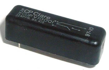
CP Clare Relay

CP Clare Relay

A special type of relay is a reed relay in which the contacts are enclosed in vacuum tubes in order to protect them from atmospheric corrosion. The operation is otherwise similar to electromechanical relays.

More recently solid state relays have come into vogue. Solid state relays are electronic components similar in function to electromechanical relays. Though initially used for low current applications, these relays are available nowadays for handling currents up to 1200A. They consist of circuits involving transistors and resistors. They have no moving parts and hence no wear out and operate much faster than electromechanical relays.

Relays are widely used in many electric and electronic control applications like overload protection of motors (circuit breakers), temperature / pressure regulators in refrigerators, railway signaling, power systems, starter for automobiles, machine tools etc. As electronic components relays are used in modems and audio amplifiers etc. Modern relays are activated by microprocessor or programmable logic controllers that have the operation logic built in.