Category Archives: LEDS

LED Light Guides Equal OLED Performance

The visual impact of OLED panels is hard to resist. Their luminosity is seductively stylish and sleek. Fashion-forward lighting designers prefer the eerily-even silky glow of the OLEDs, even though these are more expensive, have a short lifetime and can be damaged more easily than other light emitting panels. Now GLT or Global Lighting Technologies, with their edge-lit LED-based light guide technology, is about to turn the tables on OLEDs.

The latest product from GLT, a 4×4 inch LED-based light guide, demonstrates this technology specifically. Compared to an OLED panel, the GLT light guide has better durability, higher efficiency, longer life and is cheaper as well.

Applications that would normally use an OLED panel, can easily use the LED-based 4×4 inch square GLT light guide as a more durable and affordable solution. GLT has designed these light guides for use in general lighting applications and they offer diffused light output very similar to that from OLEDs, but at a much lower cost.

Offering enhanced light extraction, the light guide is very thin – only 3.5 mm. The panel itself measures only 2 mm, considerably thinner than products GLT made earlier. When in use, industry standard LEDs will typically light it up from the edges, with only a small frame concealing the LEDs. The current product gives out 250 lumens when fully powered, while the efficiency per watt is over 115 lumens.

GLT produces several types of molded light guides. All the products, including the new 4×4 backlights, are made using an efficient light extraction technology. A high-precision micro-molding process impresses optical features within the light guide. By arranging the features to provide a unique transition area, light spreads uniformly and precisely over each point across the panel. GLT has several standard patterns that they mold into the light guides. They can customize each pattern and meet any application virtually.

GLT develops their light guides in very thin packages and designs mechanical holding features into the backlights. That allows the host application to carry the entire display assembly and if that is not possible, use chip-on-flex or chip-on-glass type of assembly. That helps to reduce the parts count and material and assembly costs.

According to GTL, their light extraction technology delivers better optical performance than that offered by V-groove or stamped, chemical or laser etching and printing processes. Additionally, their process is more repeatable. After having demonstrated their light diffusion technology for a few years, GTL has now incorporated it into some of its high-end lighting products.

With their light diffusion technology, GLT offers a large variety of design options to the luminaire designers. Some of these designs can already be seen in the round 12-inch diameter pendant light. This clever design achieves results remarkably like an OLED. It uses a light guide incorporating LEDs along its inner circumference and they emit light in multiple directions.

Panasonic uses light guides from GLT in commercially available fixtures meant for mounting on ceilings. In the fixture, multiple light guides create discrete distribution patterns. These include spot lighting, downward flood lighting and upward ambient lighting within the room.

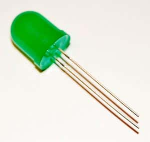
LED myths and truths

led mythsPeople tend to make up myths about things not understood properly. For example, we have been using incandescent bulbs for over 100 years now, and some think they offer the best illumination possible. Studies related to energy consumption and investigations into the spectral light distribution have debunked this myth about incandescent lamps being superior. People are readily moving over to fluorescent types and lately, to LED types for meeting their illumination requirements. However, the fear of the unknown is catching up – myths about LEDs.

As individuals and companies begin to realize that LEDs can help to save money by reducing energy consumption, some people insist that there are problems with LEDs. In reality, LEDs are simply harmless, as we discuss some of the myths associated with them.

Myth 1: LEDs Can Make You Go Blind

Recently, a study conducted on the effects of LED light on human eyes or more specifically, on human retinal cells, was published in an issue of the Journal of Photochemistry and Photobiology. According to the authors, LEDs can harm human eyes. In their experiment, the authors found that human retinal cells were affected if they were exposed to 5mW per cm2 of light from an LED for 12 hours. That is an equivalent exposure to light from a 100W incandescent lamp at a distance of 4-inches for a 12-hour period.

However, light at that intensity and duration will certainly damage anyone’s eyes, irrespective of the source. That is also the reason one must not stare at the sun for any length of time. The lens within the human serves to focus light on to the retina. This is similar to any convex lens focusing the sun’s rays on a black paper causes the paper to start burning. Staring at any intense light source for some time is likely to burn a hole in the retina.

Myth 2: Blue LEDs Are More Dangerous Than Others Are

Again, independent of the light source, bright blue light is not very good for the eyes. Blue light may cause nausea and temporary headaches and long-time exposure could damage the retina permanently.

LED makers often use a primary blue LED and use a special phosphor to down-convert it to produce white light. That has given rise to the myth that blue LEDs are dangerous and they may cause cancer. However, no evidence has been found to substantiate this. Medically, blue light does lower melatonin levels in humans leading to a weakening of the immune system. Again, no link has been found between cancer and immune systems weakened with LED light.

Myth 3: LED Brightness Is Not Enough and the Light Quality Is Questionable

This may have been true at some point of time in the past, but now, LED lights are replacing halogen lamps. LEDs are available with color temperatures ranging from warm white to daylight (2,500K t0 6,500K) and with CRI or Color Rendering Index between 75 and 90. The reference for this measurement is the incandescent bulb, which by definition has a CRI of 100. In comparison, low-pressure sodium vapor lamps have a CRI of -44, mercury vapor lamp’s CRI is 49 and quartz metal halide lamps rate at a CRI of 85.

Why is Li-Fi better than Wi-Fi?

Imagine wandering through an art gallery with your PDA. As you reach an interesting canvas, your PDA starts downloading information about the painting. When you move to another, your PDA displays content relative to the current piece of art. This is called content fencing – tailoring information to specific locations so that users receive information relevant to their current location.

Content fencing is impossible to achieve with Wi-Fi – radio waves have a far greater spreading power. However, this is eminently possible if electromagnetic waves of very short wavelength – such as optical beams – are used. We already have the necessary technology with us and it only requires converting LED bulbs into wireless access points as an equivalent of a wireless network. This is LI-Fi, allowing you to move between light sources for effectively remaining connected. At present, Li-Fi is only a complementary technology compared to Wi-Fi, but its potential benefits over Wi-Fi are huge.

Visible light spectrum has a huge bandwidth compared to the RF spectrum – in excess of 10,000 times. Moreover, visible light spectrum is unlicensed and free to use. RF tends to spread out over a large area causing interference, whereas, visible light can illuminate a tight area and can be well contained. This allows Li-Fi to attain over a thousand times the data density than Wi-Fi can achieve.

Low interference means more data can be transferred. Therefore, Li-Fi achieves very high data rates and devices using Li-Fi can have high bandwidths along with high intensity optical output. With illumination infrastructure already available in most places, it is relatively easy to plan for introduction or expansion of Li-Fi capacity with good signal strength.

The presence of illumination infrastructure also means negligible additional power requirements for Li-Fi, more so because LED illumination is inherently efficient. In comparison, radio technology requires additional components and energy to implement. Li-Fi works very well in water, but it is extremely difficult to implement and operate Wi-Fi underwater.

Even today, there is a raging debate about whether RF transmission is safe for life on Earth. Visible light does not court such controversy regarding health and safety, as it is the Sun’s rays that sustain life on Earth. Moreover, in certain environments, radio frequencies are considered dangerous as they can interfere with electronic circuitry. That is why people are asked to switch off their phones in flight.

The closely defined illumination area makes Li-Fi very difficult to eavesdrop. Unlike Wi-Fi that spreads its signals all over, even passing through walls, Li-Fi signals are confined to a specifically defined area. This makes Li-Fi far more secure as compared to Wi-Fi. Moreover, data flow in Li-Fi technology can be visibly directed according to requirement. You only need to point one device towards another to make them communicate. That makes it unnecessary to add a layer of security such as pairing, as is required for a Bluetooth connection.

Considering that LEDs operate more than 50,000 hours, it is necessary for manufacturers to add new services to the light they sell. Li-Fi offers massive new opportunities and myriad of different applications for the future communications market.

Connecting to the web via LEDs: Li-Fi

Connecting to the Internet is best done through copper wire or high-speed wireless connections. Not many are aware of an additional method – using light beams. This is accomplished not by the usual optical fiber stuff, but by using LEDs. Communication with lights is nothing new – it has been done before. The Scottish scientist, Sir Alexander Graham Bell had invented an arsenal of instruments for communication and these included Photophones.

The first instruments to use light for communication were Photophones. Now, after about 110 years after the invention of photophones and their fading into history, Professor Harald Haas is conducting experiments in wireless communication using light-centric technology. At the University of Edinburgh in Scotland, Professor Haas is using the Alexander Graham Bell building for his experiments.

Professor Haas demonstrated his vision for the future of wireless communication way back in 2011. He was using something as simple as LED bulbs for his experiments. This is also the time when the term Li-Fi was coined. Li-Fi is now used to describe bidirectional networked wireless communication using visible light as a replacement for traditional radio frequencies.

With people implementing the Internet of Things in full swing, it will not be very long before there is a spectrum crunch for the radio frequencies. In this context, light modulation and enabling connectivity through simple LED bulbs will have huge ramifications. Li-Fi can allow you to connect to the Internet as soon as you are within the range of an LED beam. Even your car headlights can be used to transmit data.

Professor Haas is working towards PureLiFi, which can offset the global struggle for the vanishing wireless capacity. PureLiFi is striving to develop and drive technology suitable for secure, reliable and high-speed communication networks. This will help to integrate data and lighting utility infrastructure seamlessly while reducing energy consumptions significantly.

One of the most interesting features of Li-Fi is its security over the conventional networking methods. Although Li-Fi is not yet available on the Internet marketing websites, companies from the security-focused fraternity are highly interested parties. That is because prying eyes of third-parties find Li-Fi significantly harder to infiltrate compared to other current networking technologies.

Li-Fi signals travel over narrowly focused beams and they cannot penetrate walls. Additionally, with LED lights, you have natural light beams; therefore, the uplink and downlink channels can be separated leading to increased security. For example, if you are browsing using two-channel Li-Fi, both beams will have to be intercepted for someone to infiltrate into your computer, provided they first gain entry into the same room as you are in.

In practice, Li-Fi networks use a desktop photosensitive unit to communicate with an off-the-shelf unmodified light fixture using infrared LEDs for its uplink and downlink channels. Within a range of about three meters, you can have uplink and downlink channels delivering a typical capacity of 5Mbps. With Li-Fi, it is possible to achieve speeds as high as 10Gbps as well. As an additional benefit, your workspace remains well lit.

Li-Fi allows you to have your content tailored before delivery. Within a single room such as in an exhibition, you could wander through various beams to pick up information relevant to your current location.

Choose the color of your led

To indicate the hue of a specific type of light source, the standard procedure is to measure its color temperature in degrees Kelvin. For example, for suggesting realistic colors of lights in a 3D scene, you can use a Color Temperature chart. Typically, the white balance of a video camera or a film stock is used as the base for relating visible colors. For this, two settings are used most commonly. The first is the indoor color balance, set at 3200K and the other is the daylight color balance, set at 5500K.

Measuring the hue of light as a ‘temperature’ was started by the British Physicist William Kelvin in the late 1800s. When heating a block of carbon, he noticed that it glowed and produced a range of different colors at different temperatures. Beginning from a black cube, it first produced a dim red light, moving to a bright yellow as the temperature increased. Eventually, it glowed with a bright blue-white at the highest temperature.

To honor William Kelvin, the unit of measurements of color temperature is degrees Kelvin, a variation on degrees Centigrade. Unlike the Centigrade scale, which starts at the temperature of freezing water, the Kelvin scale starts at -273 degree Centigrade, also known as ‘absolute zero’. However, when attributing color temperatures to different types of lights, it is usual to correlate them based on visible colors matching a standard black body. Therefore, the stated color temperature is not the actual temperature at which a filament is burning.

Now, an LED, available as a simple chip on board or COB package, can be tuned for its color temperature. The LED manufacturer Everlight has introduced this as the world’s first color-temperature tunable LED.

Immediately following brightness dimming, the next most desirable feature for users of LEDs is to be able to tune the warmth of the light output. For example, some people prefer a ‘warm’ colored light to a ‘cool’ type of illumination. Accordingly, manufacturers generally implement this feature by using multiple LEDs ranging from cool white to warm white, placing them behind a diffuser.

Everlight provides a very compact solution with its CHI3030 27V/29W series. They have packaged the LEDs behind concentric layers of phosphors. This offers different color temperatures of white as setting a precise color-temperature mix is simple now – just light up the required numbers of warn white or cool white LEDs.

Consuming 29W at 27V, the 30x30mm COB CHI3030 from Everlight is the largest such multi-chip solution for a tunable temperature LED. You can select from among different tunable ranges such as 4745-7050K for the KY Cool-White series to the 2500-5700K for the KH Warm-White series. The typical luminous flux output from the LEDs is 2990 lumens for the 5700K cool white and 2760 lumens for the 2700 warm white. Everlight makes similar other series of LEDs with fewer concentric phosphor rings that operate down to 9W.

Everlight expects such color-temperature tunable LEDs to see mainstream use within the next few years. Adding such extra color tuning flexibility allows manufacturers to calibrate their products easily and precisely at low costs.

Is there anything better than OLEDs?

Almost everyone uses a smartphone today and the displays are getting ever bigger. Larger screens are a pleasure to watch, but difficult to put inside a pocket. Therefore, Qibing Pei, a professor of materials science, is researching highly flexible and stretchable OLED displays that could allow a small elastic OLED smartphone to fit easily into one’s pocket and the screen could be expanded when viewing. That would certainly be a great help if successful, but in the meantime, there is something else, which is better than an OLED.

OLEDs require power and are expensive. Instead, carbon nanotube field emitters powering up a lighting panel are less expensive. They stimulate a phosphor in the panel to glow, much as the cathode ray tubes of the yesteryears did. The phosphor is brighter than the current OLEDs, consumes much less power compared to LEDs and is far less expensive than both of them are. Professor Norihiro Shimoi, a lead researcher at the Tohoku University in Japan is working on this technology. He uses light through a neutral density filter to illuminate nanotube field emitters to stimulate the phosphor.

Although the prototype in Professor Shimoi’s lab has yet to achieve 60-lumens per watt, it is similar in design to the flat version of the old cathode ray tube. Not expected for a commercial release before 2019, the nanotube prototype is like a lighting lamp, but with a power consumption of 1/100th of standard LED devices.

LEDs are all the rage today, owing their advantages over fluorescent and incandescent lighting because of the very low power consumption of LED based devices. With large-scale lighting, however, several LEDs have to be used together, which complicates the engineering and thermal design. On the other hand, the nanotube design is flexible enough to be formed into flat panels of any size.

Incandescent bulbs are the least efficient at a mere 15lumens per watt. In comparison, LEDs and fluorescent bulbs both produce about 100 lumens per watt. The difference is LEDs are point sources of light, whereas fluorescent bulbs spread their light over a much larger area. Organic cousins of LEDs, the OLEDs, produce about 40 lumens per watt but have the advantage of being incorporated into panels. According to Shimoi, simulating large phosphor-covered panels with electron field emitters made of carbon nanotubes will be more efficient. With their much lower power requirements, and producing 60 lumens per watt, these phosphors will potentially be brighter than OLEDs that produce only 40 lumens per watt.

Shimoi is currently working on reducing the energy loss by heat. The device employs highly crystallized carbon nanotubes and phosphors. These are coated with ITO particles. Shimoi is attempting to increase the electrical conductivity to reduce energy loss by heat. The process involves optimization of the crystallization of the carbon nanotubes along with the design of the lighting device.

Where typically, carbon nanotubes are made using semiconductor diode junctions, Shimoi has made them into excellent field emitters of electrons so that they can stimulate phosphors. Furthermore, production of these nanotubes does not require expensive clean rooms or high-temperature ovens. The nanotubes are single-walled and are grown by arcing.

Battle the Sun with a 21W LED and a Raspberry Pi

Lighting up an LED or an array of LEDs and controlling their brightness is a simple affair with the tiny credit card sized single board computer popularly known as the Raspberry Pi or the RBPi. The RBPi runs a full version of Linux and you can use it to drive an array of bright LEDs with it. If you construct it like Jeremy Blum did – he put up the LEDs on his graduation mortar board and wore the RBPi on his wrist on his graduation day – you can be sure of getting a lot of excited remarks from friends and onlookers.

Jeremy wanted to let others interact with the LED on his cap. Therefore, he developed the idea of “Control my Cap” project. His control system consists or a wrist computer comprising an RBPi together with an LCD/button interface. That allows Jeremy to monitor the status of the cap, adjust the brightness of the LEDs, change the operation mode and toggle the wrist backlight. If there is any trouble in connecting with the LED interface, the reasons will be listed on the LCD.

The RBPi is programmed to connect automatically to a list of pre-allowed WPA-protected Wi-Fi hotspots as soon as it is booted. This allows Jeremy to set the wrist interface and the LEDs to a web-controlled mode, let the LEDs take on a static color or have them follow a rainbow color pattern. The cap has a total of 16 LEDs, rated at 350mA each, with four each of Red, Green, Blue and White in four strings. A constant current driver that has a PWM control drives each string of LEDs. A separate on-board switching controller generates the 5V for the RBPi.

As the whole project is portable, a battery powers it. Jeremy used a laptop backup rechargeable battery for his project. At full brightness, the array of LEDs consumes a total power of 21W and is easily visible is bright sunlight. With an 87 Watt-hr. capacity, the battery is able to power the cap for an entire day and more. Additionally, it has a 5V USB port, which Jeremy uses for charging his phone.

Jeremy put up a mobile website controlmycap.com to allow anyone to submit colors for the color queue of the cap to be used in the web-controlled mode. In this mode, the wrist computer grabs the 10 most recently submitted colors from the mobile site constantly, displaying them on the cap. Additionally, when using a color set for the first time, the RBPi informs the requester by a tweet that their color combination is about to be displayed. The RBPi communicates with the cap via a single USB cable, which doubles as it power supply cable as well.

Jeremy used the FoxFi app on his Samsung Galaxy S4 smartphone to generate a Wi-Fi hotspot and the RBPi was able to connect to the Internet through this. The remote webserver hosting the controlmycap.com website also stores the color requests in an MYSQL database, which the RBPi queries for updating its commands.

What is LED EOS failure?

LEDs, being semiconductor components, are susceptible to failure if overstressed electrically. This is true regardless of the manufacturer and electrical overstress or EOS is the leading cause of failure of LEDs. In fact, LED components are subject to transient conditions that can cause EOS and subsequently result in a catastrophic failure.

Like all semiconductor components, LEDs too have their maximum specifications of voltage, current and power. An exposure beyond the maximum current or voltage levels can lead to EOS. Typically, a current or voltage transient, accompanying the EOS event, may cause generation of localized heat – leading to EOS failure. As with any semiconductor device, an LED also has only a limited ability to survive overstress, and this is its maximum withstanding power.

EOS must not be confused with electrostatic discharge or ESD. Electrostatic discharge is the result of a rapid transfer of static electric charge between a non-operating part and an object at a different electrical potential. ESD events typically range from pico- to nano-seconds, whereas EOS events are much slower, ranging from milli-seconds to seconds. Moreover, EOS can be only a single event, an ongoing periodic event or even a non-periodic event. Common causes of EOS are:

• A driver producing current spikes
• A driver constantly driving an LED over its maximum rated current
• A lightning strike or similar power surge from the AC mains power input
• A user hot-plugging an LED into an energized circuit

Depending on the duration and amplitude of the overstress conditions, LED failures due to EOS can vary from subtle to severe damage. For example, an LED with subtle damage may not emit light at low currents, but does so at higher current levels. On the other hand, a severely damaged LED may not emit light at all. Both may exhibit current leakage, an open circuit or a resistive short. The amount of time that it takes for an LED to be damaged by EOS, depends on the conditions of the EOS, operating conditions and the LED junction temperature.

LEDs may be classified into three types – mid-power, high-power and COB. Test laboratories typically use square-wave pulses of forward current for simulating EOS conditions in LEDs. This allows variation of all test parameters such as voltage, current, power and time. For example, pulse power levels of up to 1700W may be applied to LEDs in forward-bias mode, while the time duration may range from 0.1 to 70 milliseconds.

Most mid-power LEDs are typically enclosed in a plastic package and contain either one or multiple chips. The multiple chips may be internally connected in parallel or in series. The EOS robustness of the device depends on the internal structure. As a thumb rule, LEDs with higher light output tend to be more robust to EOS.

The EOS robustness of high-power single-chip LEDs depends on their architecture. LED device structure, such as the packaging contacts, current spreading techniques and attachment of the die, are major contributors to determining temperature rise and power dissipation and hence EOS robustness.

COB or chip-on-board LEDs are similar to high-power single-chip LEDs, with one major difference. There are bond wires connecting the top-side contacts to the chips and metal traces for current spreading, resulting in lower withstanding power as compared to other high-power LEDs.

Designing Intelligent Lighting Systems with Constant Current LED Drivers

Sunpower LLP of UK has launched 25W constant current LED Drivers that facilitate designing of low wattage project style lighting and intelligent LED lighting control systems. The company has added the driver christened LCM-25 to its existing LCM series of constant current LED drivers for 60W and 40W. Apart from maintaining its output at a constant current while meeting the LED needs, the driver can be set up at varying levels ranging from 350mA to over an Ampere with the help of a built-in DIP switch. The LCM-25 driver has been designed with a two-in-one dimming operation. It can be dimmed by a PWM control input or by 0-10VDC.

This new product comes with a host of features. The digital LCM-25DA has a push button dimming function and a DALI interface. The operating range is 180-277 VAC input. EN61000-3-2 Class C (> 50% load) sets the harmonic current limitation. Between the line and neutral, there is 2kV surge-immunity, which meets the needs of the heavy industry. The latest state-of-the-art circuit design ensures a maximum efficiency of 86%, while at the same time, cooling is by simple air convection when operating at ambient temperatures of -30°C to +60°C. No-load power consumption is less than 0.5W.

The main feature of the LCM-25 is its inbuilt PFC operation. The driver is protected against over-temperature and / or short-circuits. In either case, after constant current limiting or over-temperature protection, recovery is automatic after the fault is resolved. The driver is housed in a fully insulated plastic case. This class II power unit is designed conforming to IP 20 and without FG. Each unit can synchronize up to a maximum of 10 units. The ripple current is ±5.0% and the no-load voltage 59V.

The LCM series is housed in a totally insulated rectangular plastic case of low profile, which is rated for IP20. It is offered to the customer with several unique facilities. The first is that it is very easy to install as compared to current products of industry standard, which is to have the outputs at the rear and the inputs at the front. LCM series has been designed with the outputs and inputs on the same side. That ensures installation work remains simple and smooth, while making efficient use of the limited space while wiring. The LCM series is covered under a number of International safety regulation certifications such as the CSA C22.2 and UL-8750.

Sunpower Technology LLP is the UK wing of the Taiwanese manufacturer, taking care of all its power supply needs. The company conforms to BS-EN-ISO 9001:2008 and its factories are certified under ISO certifications 14001 and 9001. Sunpower has been striving for improvements on a continuous basis with the aim of providing customer satisfaction. Even customers buying low volumes are provided technical support and affordable price. The latest LED driver, the LCM-25 has enabled designing low wattage intelligent LED lighting systems. With a global reach, the product is sure to capture a significant share of the market.

ByteLight LEDS provide location based service

Not so very long ago, the friendly neighborhood supermarket had a security guard who would greet you in recognition and the store assistants could guide you since they knew what you usually bought. However, the introduction of huge shopping malls with their multiple floors has done away with anyone able to recognize even frequent customers, making the whole affair of shopping completely impersonal.

However, things are about to change. GE Lighting and ByteLight are harnessing the next generation of LED lighting fixtures to communicate with the smart devices of shoppers while they are in-store. Very soon, shoppers will be greeted with personal messages starting from the parking lot. As shoppers move about within the store, they will receive an easy-to-follow map on their devices to help them optimize their shopping time. The store will offer repeat customers a personalized shopping list along with information on promotions and coupons based on their shopping history, current position and direction on the aisle.

Customers will be able to see reviews, play product information videos and connect with virtual associates on-demand to make their brand choice easier. ByteLight has developed this technology by combining VLC or Visible Light Communication, BLE or Bluetooth Low Energy and inertial sensors. They can determine not only the precise location of the shopper on the aisle, but even the direction the person is facing.

The patented ByteLight LED indoor location technology offers several advantages to both shoppers and retailers. It brings the retailer faster ROI as existing lighting infrastructure can be used and no additional equipment is necessary. It has an accuracy of three feet in determining the location and direction of the shopper anywhere there is light. It can connect to any shopper who has a mobile device equipped with Bluetooth and/or camera. ByteLight, being powered by the light fixture, does not require batteries and hence, is maintenance free.

According to Dan Ryan, the CEO and Co-founder of ByteLight, the value proposition for digital LED lighting is shifting from providing illumination to offering innovative services and applications. They are reinventing LED lighting to provide a platform for indoor-location services. Not only will this revolutionize the in-store shopping experience, LEDs will play a strategic role in the experience of customers in connected retail.

GE is providing the lighting fixtures that ByteLight will be using for their location-based services. It amply demonstrates how simple LEDs can be used beyond their traditional ROI of maintenance and energy savings to change the fundamental way of how people shop by combining information with location.

Shoppers will be using an opt-in application on their smartphones or tablets. The app will be powered by ByteLight and together with the indoor location technology embedded within the GE LED fixtures, will deliver to the shopper high value applications based on their current location and the items they are presently watching.

This comprehensive approach will help retailers reach out to an even broader number of shoppers across the largest area – starting from the parking lot and continuing anywhere within the store where there is LED light. That means, retailers will have continuous ROI on their GE lighting and at the same time, this will provide a strategic platform for the futuristic connected retail store.