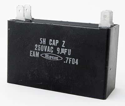
 If you are using an AC pump to raise water from a sump to an overhead tank, chances are it uses a squirrel-cage type motor, which needs a capacitor to make it work. This is true for single-phase motors, where the capacitor creates an artificial second phase necessary to generate the rotating magnetic field and make the rotor start spinning. Once the rotor starts rotating, the interaction between the stator and rotor keeps the magnetic field spinning.
A single-phase motor has a primary winding and a secondary winding. If connected to the AC supply without the capacitor, both windings produce magnetic fields of the same phase resulting in zero torque. With a capacitor connected in series to the secondary winding, the magnetic field it produces lags behind the magnetic field generated by the primary winding. This difference in phases creates a starting torque and the motor starts to rotate.
Capacitors that allow a motor to start rotating are called start capacitors. Smaller motors usually have the start capacitor permanently connected in series to the secondary winding. Big motors require a larger capacitor to help them generate the starting torque, but they run more efficiently with a small capacitor in place, called run capacitor. Often both capacitors are housed in the same can, which then has three terminals in place of the customary two. Such motors have a centrifugal switch to disconnect the start capacitor when the motor has reached 70-75% of its full speed. Start capacitors are typically of high value of 100 or more microfarads, while run capacitors are smaller, of about 25-47 microfarads.
You will find motors with large start capacitors being used for several applications where it is necessary to generate considerable torque to begin moving the load. Such applications include mechanical conveyors, belted blowers and commercial garage door openers. These are mostly electrolytic capacitors, housed within a plastic or metal can. Inside the can are two metal foils rolled up with a flexible paper-like insulation separating the sheets. The paper, soaked with an electrolyte, forms the dielectric of the capacitor. The two metal foils are connected to two terminals. The assembly is sealed with epoxy and the two terminals are available for external electrical connection.
Large HVAC units sometimes need two run capacitors, because they have both a fan motor and a compressor motor. To save space, manufacturers combine the two physical capacitors into a single can. Such dual capacitors have three terminals and they are usually marked as Common, Fan and Compressor.
You will find a variety of combinations for dual capacitors, for example, 40 + 5uF, 370V or 100 + 25uF, 440V and others. Their shapes can be cylindrical with a round or oval cross-section. A capacitor’s ability to hold charge is measured in microfarads. As electrolytic capacitors age, their capacity reduces. That results in the motor failing to start or run at less than full speed.
Motors are not fastidious about the capacitance value of the capacitor used for starting. However, when replacing a faulty capacitor, you must never use a replacement that has a lower voltage rating. Always use a part with a voltage rating that is the same or higher than the rating of the capacitor you are replacing. Of course, it’s always preferred to replace a capacitor with another that has the exact electrical specifications for the best results – both in performance and safety.
