Monthly Archives: August 2013

Let Raspberry Pi Make It to the Movies through XBMC

The Raspberry Pi is capable of HD video. Won’t it be great if you could playback your Blu-ray movie collection through Raspberry Pi on to your HD TV or monitor? That would be possible if you knew how to let Raspberry Pi run XBMC.

What is XBMC?

XBMC is a software media player and entertainment hub, and the best part is you do not need to pay anything to get it, as XBMC is free and open source (GPL). As a media player, XBMC has almost everything you will need, right from TV and remote controls, to support for digital media files from local and network storage media including the internet. You can play and view most digital media files such as podcasts, music and videos.

There is not much that XBMC misses. You get to play all your music files in mp3, flac, wav and wma formats. You can watch movies in all the main video formats including streamable online media. You can keep track of your progress of season views and episodes of TV shows. You can import pictures into a library for browsing as in a slideshow, and you can record live TV all from the nice GUI interface that XBMC has.

Step 1: Download XBMC

You will need to download an image of XBMC, which is available as “debian-xbmc-24-04-2012.zip” and you can get it here. Unzip the file to get to the image.

Step 2: Write the Image on to an SD Card

If you are on Linux or OSX, open up a terminal and navigate to the folder containing the downloaded image. To write to an SD card, you have to enter the following command –

dd bs=1m if=debian-xbmc-24-04-2012.img of=/dev/rdisk1

Note that ‘/dev/rdisk1’ depends on the type of PC you are using.

If you are still on Windows, you need the Win32DiskImager utility program to write the image to the SD card in the device box.

Step 3: Make Space on the SD Card

The image written to the SD Card will be about 2GB, leaving about 60MB free space. This is not enough for XBMC to operate properly. Use Gparted, which is the Debian partition editor to expand the free space. Assuming you have a 16GB card on which you installed the OS and XBMC, there is still 13GB space left over. Go into Gparted, and expand the Linux swap partition to cover the 13GB. That will allow XBMC to use the free space.

Step 4: Start Action

Plug in the SD card into your Raspberry Pi, and boot it up. At the command prompt, type –

XBMC

and you should be able to see the following –

Note that XBMC is still an alpha release, and is somewhat fragile. It might lock up or not start at all. This is expected and you may need to restart Raspberry Pi over again to get XBMC play properly.

Try out all your music, video and other programs including your favorite TV shows, and you will be surprised at the quality of the output from the combination of XBMC and Raspberry Pi.

How RTPs Help To Save Expensive PCBs from Thermal Runaway PowerFETs

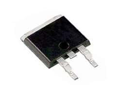
powerfetAlthough powerFETs or power Field Effect Transistors are very robust devices used in the automotive industry – they have their limitations. In the automotive environment, powerFETs go through the tortures of extreme temperature variations together with severe thermo-mechanical stresses. They face noisy short circuits, high arcing, intermittent shorts as well as inductive loads. These shocks can fatigue the device over time, and it can fail in a short, an open or resistive mode.

For example, if the maximum operating voltage of a powerFET is exceeded, failure happens very quickly. The powerFET goes into an avalanche breakdown once the voltage rating goes beyond the maximum allowed. If the energy within the transient overvoltage is more than the rated avalanche energy level, the device will start to fail resulting in generation of smoke, flame or it may even be de-soldered.

In some cases, the powerFET while failing may generate precarious temperatures through I2R heating. This may cause a thermal runaway for the device, but the resulting current may not be large enough to cause failure of a standard fuse protecting the powerFET. This mode of failure is of particular concern, for not only the powerFET, but also for the PCB or the Printed Circuit Board. A power of as little as 10 Watts may generate localized hot spots of above 180°C, which can damage the glass PCB’s epoxy structure leading to a thermal event.

Tyco Electronics has developed a Reflowable Thermal Protection or RTP, which is a reliable and robust surface mount thermal protector to prevent thermal damage on PCBs caused by failing power electronics. This is a secondary thermal protection device, which can replace several components such as redundant powerFETs, heavy heat sinks and relays currently used for such protection in the automotive designs.

To work effectively, the RTP device has to be placed in series and on the power line, very close to the FET. This allows the device to track the temperature of the FET and disrupt the current by opening the circuit before the thermal runaway condition generates a thermally destructive condition on the PCB. Under normal conditions, the RTP device has a low resistance, typically about 0.6mOhm.

Whenever the RTP device detects the generation of unsafe temperatures because of the failure of a power component or any other board defect, it interrupts the current and prevents a thermal runaway condition that could lead to critical damage. An RTP200 device typically opens (high resistance condition) at 200°C, which is a temperature above the normal operating temperature, but below the Lead-free solder reflow temperature.

It may seem like a paradox that the RTP device operates at 200°C but can withstand Lead-free soldering temperatures of 220°C. This is because the RTP is not in an active state unless it has been armed by passing a specific current through it for a specified amount of time. Before it is armed, the RTP can withstand three Lead-free solder reflow steps before it operates. The electronic arming procedure is one-time only and can be implemented to occur automatically or during system testing.

The Emergence of BBB: the BeagleBone Black

Many a time we have wished our bulky PCs that occupy so much of the desktop space could somehow be magically squeezed into a portable unit. Although such systems are there including the new smartphones and tablets, their sky-high prices are very discouraging for most of us.

Despair not, for such a package has arrived and is well within the reach of an average person’s pocket. Moreover, if you are technically oriented, you could build one yourself. Texas Instruments has provided the core processor and BeagleBoard has provided the packaging. The result is the low-cost, low power, fan-less, single-board computer called the BeagleBone, a latest addition to the BeagleBoard family.

The low-cost, fan-less, low power, single-board computers from BeagleBoard utilize the Texas Instruments’ OMAP3530 application processor. This offers laptop like performance and facility for expansion, without the bulk, the noise and the expense that are typical of desktop machines. Within the OMAP3530, there is a 600MHz ARM Cortex-A8 Micro Controller Unit (MCU), which predicts branches with high accuracy and a 256KB L2 cache memory.

The on-board USB 2.0 OTG port serves a dual purpose; you can transfer data out from the board or allow the board to read data in from an external source. Although the board has a separate 5V DC power socket, power to the board can be supplied through the USB port as well. The board also has a mini-A connector, to which you can connect standard PC peripherals using a standard-A to mini-A cable adapter. A DVI-D connector allows a HDMI display to be connected using a HDMI to DVI-D adapter. The third connector is the MMC/SD/SDIO card connector. To give you the best graphics experience, the BeageBoard has a state of the art POWERVR graphics hardware, which will render 10 million polygons each second.

For people who were not satisfied with the power of the BeagleBoard single-board computer, BeagleBoard has added the BeagleBone Black or BBB. This is the newest addition to the BeagleBoard family, and continues the saga of the low-cost, low power, single-board computers. To provide the additional features, an advanced MCU, the Texas Instruments’ Sitara AM3359 has been used. This is an ARM Cortex-A8 32-bit RISC processor, featuring a speed of 1GHz, and gives BBB the power along with a 512-MB DDR3L 400MHz SDRAM and 2GB 8-bit eMMC on-board flash memory. This frees up the micro SD card slot for further expansions.

The 92-pin headers are Cape compatible, meaning the existing family of cape plug-in boards can be used as well. The on-board HDMI allows direct connection to monitors and TVs. External electronics circuitry can be controlled by the UART0 serial port. For connecting to the Internet, a 10/100 RJ45 Ethernet connector has been provided.

You will need the latest Angstrom distribution eMMC flasher to load the latest Linux distribution. This is a 4GB image, that has to be uncompressed using unxz and written to a micro SD card. Connect an HDMI monitor, and after plugging in the micro SD card in the slot of the BBB, you can power on your single-board Linux computer. Take care to hold the boot button on while powering, and watch the LEDs on the BBB flash and then stay on.