In the presence of different digital signals that need to be combined to make a logical decision, engineers use different types of digital logic gates. Usually, these gates have several inputs but a single digital output. Where a larger logic gate function or a sequential or combinational circuit is required, it is usual for individual logic gates to be connected together.
Digital logic gates in standard commercial form are available in two basic forms or families – TTL or Transistor-Transistor Logic and CMOS or Complementary Metal-Oxide-Silicon. An example of the TTL types is the 74xx family and the 4xxx family for the CMOS types. The notation TTL or CMOS is the logic technology that manufacturers use for the Integrated Circuit or IC or chip as commonly known.
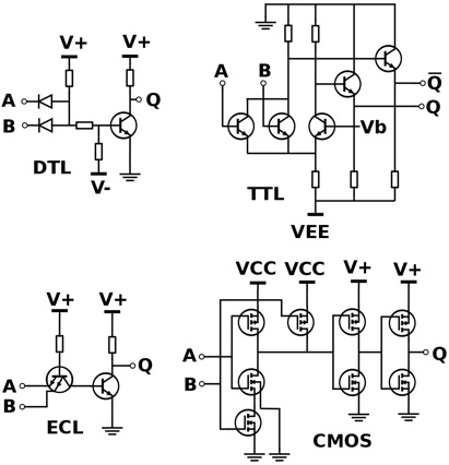
The difference in the two families depends on the type of transistors used in making these ICs. While ICs using the TTL logic make use of PNP and NPN type of Bipolar Junction Transistors, the CMOS logic uses JFET or complementary MOSFET type of Field Effect Transistors for their input as well as output circuits.
Apart from the TTL and CMOS technologies, other simpler types of Digital Logic Gates also exist. Some involve the use of diodes, resistors and transistors strung together as RTL or Resistor-Transistor logic gates. Other types are DTL or Diode-Transistor logic and ECL or Emitter-Coupled logic. However, these are far less common compared to the popular TTL and CMOS family, owing to the lower power consumption and heat dissipation of the latter types.
It is usual for ICs to be grouped together into families based on the number of gates or transistors they contain. For example, a single OR gate may be made up of only a few individual transistors, whereas complex micro-controllers have several thousands of individual transistor gates. This leads to integrated circuits being classified as Small Scale Integration or SSI, Medium Scale Integration or MSI, Large Scale Integration or LSI, Very-Large Scale Integration or VLSI, Super-Large Scale Integration or SLSI and Ultra-Large Scale Integration or ULSI. Most complex micro-controllers, video processors, GPUs, CPUs, PICs & FPGAs are examples of ULSI containing several million transistors.
The most modern level of integration, representing the increasing complexity of modern digital circuits, is the Systems-on-Chip or SOC. Here, a single piece of silicon forms the base for individual components such as IO logic, peripherals, memory and the microprocessor. This represents a complete electronic system within the individual single chip.
The Digital Logic Gate forms the basic building block for construction of the entire field of digital electronic circuits and all microprocessor based systems. Digital Logic Gates fundamentally perform logical operations such as AND, OR and NOT on binary numbers represented by digital voltage signals.
The digital logic design recognizes only two voltage levels or states. These are generally referred to as the True, High or Logic “1” and False, Low or Logic “0” states. In Boolean algebra and in standard truth tables, the digits “1” and “0” represent the two states. In terms of voltages, digital logic systems typically use a “Positive Logic”. Here, the level “0” is represented by 0V or ground potential and a higher voltage such as 1.8V or 3.3V or 5.0V represents level “1”.