Tag Archives: gpio

Expanding the GPIO on the Raspberry Pi

Although the single board computer the Raspberry Pi or RBPi has nearly 26 GPIO pins in its earlier models and 40 in its latest, there are times when the project demands more of them. In such cases, a GPIO expander is the only solution, and the MCP23S08, a device that Microchip Technology makes provides an easy way to expand the IO pins of a micro-controller using only a 2-wire serial interface.

The MCP23S08 works with the I2C protocol as a slave device, providing 8-bit, general purpose, bi-directional IO expansion for the I2C bus. It supports a 7-bit slave addressing, with the control byte acting as the read/write bit. Of the slave address, the MCP23S08 fixes the four most significant bits to 0100. This leaves the remaining three bits to be defined by the user as the address bits. Therefore, one can connect up to eight MCP23S08 devices on a common I2C bus at any one time.

It is possible to configure individual bits of the 8-bit GPIO port as either input or output. At the same time, it is also possible to enable the internal pull-up resistor on the port pins to interrupt-on-change. A set of configuration and control registers control these operations. Each resistor has its own address and its power-on reset value, as listed on the datasheet of the MCP23S08.

The first register is the IO direction register, and controls the direction of the data IO. On setting a bit in this register, its corresponding pin assumes an input direction, and if the bit is clear, its corresponding pin works like an output.

With the input polarity register, the user can configure the polarity of the corresponding GPIO port bits. When he/she sets a bit on this register, the corresponding GPIO register bit stores the inverted value present on that pin.

Interrupt-on-change control register controls this feature for each pin. When the user sets a bit on this register, the corresponding pin becomes capable of interrupt-on-change. Of course, for enabling this feature, the user must also configure the INTCON and DEFVAL registers as well.

Interrupt control or INTCON register controls the manner in which the associated pin value compares for the interrupt-on-change feature. If the user sets the bit, MCP23S08 compares the corresponding IO pin against the associated bit in the DEFVAL register. If clear, the MCP23008 compares the corresponding IO pin to its previous value.

The default comparison value or DEFVAL register is for configuring the default comparison value. If the user enables a bit in this register, and the associated pin has an opposite value, it will cause an interrupt.

The PI-SPI-DIN series of IO modules has the RBPi reading 2 modules of eight isolated digital inputs for a total of sixteen inputs and controlling four modules of four relay outputs for a total of 16 relays, all using the IO expander chip MCP23S08.

As the RBPi can select only two chip-select lines, each of the PI-SPI-DIN modules has a jumper selection of five chip selects. The two address lines of the MCP23S08 need to be enabled in the setup routine while determining the port pins as inputs or outputs.

Types of HATs suitable for the Raspberry Pi

Among several versions of the low-cost, versatile, single board computer, the credit card sized Raspberry Pi or RBPi as it is commonly called, the latest is the Model B+. Along with many new features, the RBPi Model B+ is designed to make intelligent use of expansion cards. Keeping in view of the appendage called a β€œhat” that many people place on their heads, the RBPi too has expansion cards known as HATs. These are Hardware Attached on Top, and they work by sitting atop the single board computer.

In reality, the RBPi is a bare-bones computer, where only the most essential peripherals are present on-board. This not only helps to keep the prices down, but also allows the primary user to start work with the SBC without being unnecessarily distracted. The primary objective for the makers of the RBPi was to let school children learn about computer programming. The RBPi achieves this objective excellently by allowing the students to start with the bare minimum requirements. They progress by using different HATs to get additional functionality. The advantage is the RBPi behaves as the revolutionary fundamental building block on which widely differing concepts can be easily proven.

Any sort of physical computing with the RBPi generally necessitates setting up extra hardware. Instead of soldering the components directly to the GPIO pins, it is prudent to add the necessary hardware in the form of an expansion card or a HAT, which you simply plug in. To use the HAT, the user has to modify the software suitably, mainly by installing the required drivers and configuring them.

The original models of the RBPi, the A and B, are really not conducive for expansion boards. The 26-pin ribbon cable connector provided on-board offer only the GPIO pins. However, several companies have made expansion boards suitable for direct plug-in to the connector, and they sit on the RBPi, making an electronic sandwich.

With introduction of the RBPi Model B+, the most noticeable change was the transformation of the GPIO connector to a 40-pin PCB header. The first 26 pins of the new header have remained identical to those on the models A and B – maintaining backwards compatibility. That allows HATs developed for the older models to be also used on the RBPi Model B+. The Model B+ has two new pins, ID_SD and ID_SC to allow connecting a serial EEPROM. That allows proper identification of the HAT and RBPi can load the necessary drivers for it. Therefore, as long as the manufacturer designs the HAT or the expansion board correctly, RBPi can configure it automatically.

The Raspberry Pi Foundation has issued specifications that all boards should follow for compatibility with the new model. According to these specifications, an expansion board can be called a HAT only if the board supports the two new pins and has an EEPROM for identification. This identification must include information about the vendor, the GPIO map and the device tree. The board must also conform to the mechanical dimensions specified and not overload the power supply of the RBPi. However, HATs need only meet the minimum specifications, which leave plenty of scope for innovation and stacking.

An Introduction to the Raspberry Pi GPIO

gpioThe highly popular, tiny, single board computer, the Raspberry Pi or RBPi has a row of pins along one of its board edges close to the yellow video out socket. These are its general purpose input/output or GPIO pins and one of its very powerful features.

The RBPi needs these pins to interact with the outside world physically. To simplify things, you can think of them as switches that you can control as inputs or that the RBPi can control as outputs. Of the 26 pins available, nine are for power and ground, while the rest of them (seventeen) are the GPIO pins.

You can set up these pins in different ways to interact with the real world and do fantastic things. It is not strictly necessary that the inputs come only from a physical switch. It might be the input from a sensor, a device or even a signal from another computer, for example. You can use the outputs for anything from turning on an LED to sending data or a signal to another device.

For example, if your RBPi is on a network, you can remotely control devices that are attached to it, while those devices can send data back. The RBPi is ideal for connecting to and controlling physical devices over the internet and that is powerful and exciting thing.

Playing around with the GPIO can be safe and fun, provided you follow some rules and instructions. It is very easy to kill an RBPi if you randomly plug wires and power sources into it – therefore the caution. You could also do a lot of damage if you connect things to your RBPi that use up a lot of power. For example, connecting LEDs to your RBPi is fine, but connecting motors are not. For those newly introduced to the RBPi, using a breakout board such as the Pibrella is a safer alternative than to use the GPIO directly.

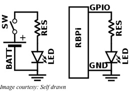
For using the GPIO as an output, the RBPi replaces the power source and a switch in the external circuit. For instance, when an LED is to be lit up, generally a battery is used as a power source and a resistance is necessary to limit the current flow. A switch offers the means to turn the LED on or off. All these are connected in series for the circuit to operate.

To control the LED from an RBPi, you can safely omit the battery and the switch from the circuit. You can individually turn on or off each output pin of the RBPi. Additionally, when the pin is on or digitally HIGH, it outputs +3.3V and when it is off or digitally LOW, it outputs 0V. The next step involves instructing the RBPi when to turn the pin on and when to turn it off.

GPIO inputs on the RBPi require some more work. The RBPi senses an input signal on a pin based on whether there is adequate voltage present. The voltage presented by a sensor must be within levels specified for the RBPi to sense it as digitally HIGH or digitally LOW. Sensing analog or continually varying signals usually needs another interface called ADC or Analog to Digital Converter.