When current flows through a resistor, part of the electrical energy is converted into heat that gets dissipated into the surroundings. If the heat generated is not quickly removed, it can permanently damage the electronic circuit. Heatsinks are devices that are capable of removing the heat from electronic devices and speedily dissipate it into surroundings.
Heatsinks can be passive or active devices. Passive heat sinks consist of fins made generally

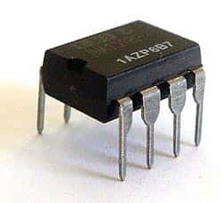
Voltage Regulator in a Heatsink
of aluminum that provide a large surface area for heat dissipation. Active devices in addition have fans that circulate the air around the sink for faster removal of heat. The heat dissipation in a heatsink takes place principally through convection either natural or forced.
Heat transferred through convection is proportional to the temperature difference between the heatsink and the surroundings. The constant of proportionality is called convection coefficient. Mathematically, q = h x A x ∆t, where q is the heat dissipated by convection, h is the convection heat transfer coefficient, A is surface area and ∆t is the temperature difference between the heat sink and the surroundings. The coefficient h is a function of velocity of air circulating around the heatsink among other things. Thus higher the speed of air circulating around the heatsink faster is the heat dissipation.
Heatsinks are widely used for cooling electronic devices and the surrounding circuit like the CPU in a computer. With the need to make electronic devices more compact and powerful, the need to make high capacity heatsinks is increasing. Modern heatsinks are manufactured by extrusion, die casting, cold forging etc. Heat pipes have been used in heatsinks as they are lighter and more efficient compared to solid pipes of same size. Anodized aluminum is the most common material used in making heatsinks, although copper, silver and even gold have been used.


 lot of study was done in the field and the initial operational amplifiers, based on vacuum tubes, were a result of the research done in Bell labs. By 1960’s, vacuum tube op amps had given way to solid state devices and hybrid operational amplifiers were entering the scene.
 Here are some other uses: