Tag Archives: circuits

The humble cable assembly

In a project, the major focus is on active components, circuit design and software, in that order. However, what we tend to overlook is the humble cable and connectors that link all the components together. Nonetheless, along with the more glamorous components, the humble cable assemblies also define the success and reliability of your project.

Active devices and test equipment, being very tangible, always seem to command greater respect compared to the attention bestowed on the almost invisible cable and connector assemblies. This is true in both the prototyping and production cycles. However, this may prove unwise in the long run. Although wireless connectivity is catching up fast, in reality, hard-wired signal interconnects are still irreplaceable and indispensable parts of nearly all systems.

Once design engineers work on the gigahertz and higher ranges in their projects, it gets more challenging for them as cable assemblies play a more active role, both practically and figuratively. The importance of cables and connectors can be seen in RF/microwave-centric web sites and publications that devote more than one-third of their ads and content to the subject. In the high-frequency world, phase matching between two nominally identical assemblies is very often critical. This arena talks about second- and third-order parameters and the temperature coefficient of the cable’s specification gains importance. High-frequency designers treat cable assemblies with respect. For them, the assemblies are energy waveguides that are carefully engineered and modeled with precise dimensions, tested and fabricated.

Just as there are many cases of counterfeit components, mostly ICs and sometimes passive, Cabling and Installer have reported fake cable assemblies as well. In fact, this was one of their top 10 articles in 2014. Fake cable assemblies do not fully meet the operating specifications. They may somehow work, but fall short at higher data rates, or they cannot provide the specified power when used for PoE.

Not only the electrical performance, fake cable assemblies compromise safety as well. In most installations, a cable’s insulation is very important factor, as it must be fire-rated so as not to support combustion. This is usually not noticed unless a fire breaks out. Some fake assemblies even substitute the necessary copper wire with a brittle aluminum core and copper cladding.

It is very easy to make fake cables, stamping them with almost any rating required. Very few people test and verify the cable performance when faced with falling data rates and rising BERs. In most cases, we remain content with the Cat5/UL rating stamped on the cable, taking them as given. This is a concern that is bothering not the high-frequency instrument manufacturers alone, but also the audio industry, the aircraft industry and electrical distribution companies. Who can say the OFHC or Oxygen Free, High Conductivity audio cable is not actually a plain copper cable slapped with an OFHC label?

With the world now reaching out to 100GHz and beyond, cables are getting thinner, tinier, with hair-thin wires, and corresponding match-head sized connectors. At such high frequencies, every bend radius, routing guide stress, torque and abrasion from sharp edges becomes important and critical.

Why Does An Inductor Need A Fly-Back Diode?

An inductor usually stores energy when current flows through it, and releases it once the current flow stops. When the power supply to an inductor is suddenly reduced or removed, the inductor generates a voltage spike, which is also referred to as an inductive fly-back. Any current flowing through the inductor cannot change instantly and is limited by the time constant of the inductor. This is similar to the time constant of a capacitor, which limits the rate of change of voltage across its terminals.

The time constant of an inductor is the product of its inductance in Henries and the resistance present in the circuit. Usually, all current can be considered to have been dissipated within five time constants once the inductor has been disconnected. The process of inductive fly-back is best explained with an example – a 10H inductor in series with a 10Ω resistor, is charged long enough through a closed switch so that maximum amount of current is now flowing through the circuit.
When the switch is suddenly opened, the current flow has to come to zero within five seconds (five time constants). However, the switch opens far faster than five seconds, which implies current flow through an open switch – an impossible situation.

However, this can be explained by considering the switch to be bridged by air resistance of an extremely high value – 40,000,000 MΩ. Therefore, the inductor, in trying to keep the current flowing through the circuit will send a minute amount of current through this big air-resistor. According to Ohm’s law, every resistor will have a voltage drop commensurate with the current flowing through it. To maintain the current flow in the same direction, the inductor will have to change the polarity of the voltage across itself.

At the instant the switch opened, the current through the circuit would have been about 99% of the maximum current. Such a current multiplied by the extremely high resistance of the air gap will result in a huge voltage. Such a large voltage drop is possible because the inductor has stored energy, which it will use to create a very large negative potential on one side of the gap. That ensures the current flow will match the dissipation curve of the inductor. This is the origin of the huge fly-back voltage spike associated with the sudden disruption of current through an inductor.

The fly-back voltage generated by an inductor can be potentially damaging. Not only can the arc generated damage the insulation of the inductor, it can damage the switch or component being used to open or close the circuit. The arcing effect has been dramatically captured in this short video.
The use of a fly-back diode precludes the possibility of damage from an inductive fly-back. The diode provides a path for the inductor to drive the current flow once the circuit has been opened. As long as the circuit is closed, the diode is reverse biased and does not contribute to the functioning of the circuit.

When the switch opens, the inductor has a path to maintain the current flow through the diode. As the inductor reverses its polarity, it forward biases the diode, which then conducts current for the five time constants, until the current reduces to zero. That prevents the voltage spike.

What is a heatsink?

When current flows through a resistor, part of the electrical energy is converted into heat that gets dissipated into the surroundings. If the heat generated is not quickly removed, it can permanently damage the electronic circuit. Heatsinks are devices that are capable of removing the heat from electronic devices and speedily dissipate it into surroundings.

Heatsinks can be passive or active devices. Passive heat sinks consist of fins made generally

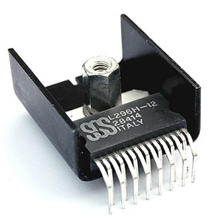
Voltage Regulator in a Heatsink

Voltage Regulator in a Heatsink

of aluminum that provide a large surface area for heat dissipation. Active devices in addition have fans that circulate the air around the sink for faster removal of heat. The heat dissipation in a heatsink takes place principally through convection either natural or forced.

Heat transferred through convection is proportional to the temperature difference between the heatsink and the surroundings. The constant of proportionality is called convection coefficient. Mathematically, q = h x A x ∆t, where q is the heat dissipated by convection, h is the convection heat transfer coefficient, A is surface area and ∆t is the temperature difference between the heat sink and the surroundings. The coefficient h is a function of velocity of air circulating around the heatsink among other things. Thus higher the speed of air circulating around the heatsink faster is the heat dissipation.

Heatsinks are widely used for cooling electronic devices and the surrounding circuit like the CPU in a computer. With the need to make electronic devices more compact and powerful, the need to make high capacity heatsinks is increasing. Modern heatsinks are manufactured by extrusion, die casting, cold forging etc. Heat pipes have been used in heatsinks as they are lighter and more efficient compared to solid pipes of same size. Anodized aluminum is the most common material used in making heatsinks, although copper, silver and even gold have been used.

What is Transistor-Transistor-Logic – TTL?

TTL Transistor-Transistor-Logic

TTL Transistor-Transistor-Logic


TTL or Transistor-Transistor Logic is a type of digital circuit that is made from BJT or bipolar junction transistor along with resistors. Both the amplifying function and the logic gating function are carried out through transistors, thus the name transistor-transistor logic.

TTL is used for many applications like industrial controls, computers consumer electronics, test equipment, synthesizers and more. The TTL designation is also used in some places to imply ‘compatible logic levels’ even if they are not directly associated with transistor transistor logic circuits.

James Buie invented the Transistor Transistor Logic in 1961 and the first Transistor-Transistor Logic devices were made in 1963 in Sylvania. These devices were called the “Sylvania Universal High-Level Logic family” and were used within controls for the US Phoenix missile. In 1964 Texas Instruments produced ICs of 5400 series and later on, the 7400 series which made the Transistor-transistor Logic devices popular amongst electronic system designers. The 7400 series went on to become the industry standard. Many companies like AMD, Motorola, Intel, Fairchild, Siemens, National Semiconductor made compatible parts.

The TTL circuits were low cost which made them highly practical for using digital techniques in tasks which were earlier done through analog methods. One of the first computers that was built, in 1971, made use of the transistor transistor logic instead of a microprocessor chip which at that point of time was not available. With time incremental improvements in power consumption and speed were made, and the last popular series was the 74AS/ALS Advanced Schottky was made available in 1985.