Tag Archives: EMI

Anechoic Chambers for RF and Electromagnetic Testing

As the meaning of anechoic is ‘without echo’, an anechoic chamber represents a room that has minimal wave reflections from the floor, ceiling, and walls. Anechoic chambers are, therefore, suitable for testing Radio Frequency or RF, electromagnetic interference or EMI, and electromagnetic compatibility or EMC. Special materials on the floor, ceiling, and walls of the chamber help to absorb electromagnetic waves.

Another type of anechoic chamber is suitable for audio waves. The design of such chambers is meant for testing audio recording. The floor, ceiling, and walls have special material and their design helps to absorb sound waves.

A wide range of application areas requires accurate measurements of the electromagnetic spectra. For instance, the testing of an antenna requires measuring the electromagnetic energy levels that it is sending or receiving in all directions. Engineers call this the radiation pattern of the antenna, and the pattern can be in three dimensions, or in the principal plane.

When testing an antenna in an anechoic chamber, engineers use a reference antenna for transmitting a known level of power. They rotate the antenna under test to a known angle and allow the measurement system to record the power it receives. By rotating the position of the antenna under test to a different angle, they can take another measurement of the power it is now receiving. By combining all the measurements, they can form a polar plot representing the radiation pattern in that elevation or azimuthal plane.   

Conducting this exercise in the open area test site offers several disadvantages.

The test environment may have extraneous electromagnetic waves that the antenna can pick up along with the test signal. This will introduce errors in the measurement. A variety of sources can supply these extraneous waves, including air traffic, cell phones, FM radio transmitters, and more.

Moreover, weather conditions like rain and wind may also easily affect outdoor measurements of electromagnetic radiation.

Additionally, there can be reflections from nearby structures and the floor. The antenna under test will likely pick up these unwanted reflections as well.

Testing inside an anechoic chamber helps engineers avoid the above disadvantages. Typically, anechoic chambers use metal walls as a shield for preventing external radio signals from impinging on equipment inside the chamber. Special RF absorbing materials on the interior walls, floor, and ceiling of the chamber help in absorbing unwanted reflections of radio waves.

In fact, a shielded and non-reflecting anechoic chamber represents an infinitely large room, where the reflections do not reach the device under test, thereby enabling repeatable and accurate measurements.

Available anechoic chambers range in size from a typical room to a small tabletop enclosure. In fact, some anechoic chambers are so big engineers can easily walk inside, while some are as large as an aircraft hangar.

Pyramidal foams with a loading of conductive carbon often cover the internal surfaces of anechoic chambers. The tapered structure of the pyramidal shapes ensures minimal wave reflections for radio waves hitting them, while the presence of conductive carbon helps to absorb the waves. The RF absorbing material converts the absorbed incident electromagnetic energy to heat.

Magnetic Sheets Prevent Noise from Spreading

Electrical or magnetic noise is a byproduct of electrical activity within an operating device, and it causes several types of nuisance. A device generating a strong electrical or magnetic interference (EMI) can influence a nearby device, making it malfunction or even prevent it from operating at all. The extent to which a device affects another with its electrical or magnetic fields is called its Electromagnetic Compatibility, while the extent to which a device is susceptible to external electrical or magnetic fields is called its Electromagnetic Susceptibility.

Engineers make efficient use of such electromagnetic characteristics of devices. For instance, smartphones and other devices have wireless charging technology and near-field communication. Both make use of electromagnetic fields, the first to charge the device, and the other, allowing communication with nearby devices, both without any physical connection.

The above requires effective shielding and suppression of noise from electronic products. Magnetic sheets offer one such method, with the TDK Corporation offering the latest types of noise suppressing sheets, the IFM10M, a new addition to its Flexield series. TDK claims its new magnetic sheet suppresses noise over a frequency range of 500 KHz to 10 GHz. This is useful for several types of electronic devices, such as industrial terminals, point-of-sale systems, stylus pens, notebooks, tablets, and smartphones.

Featuring a laminated design, the IFM10M series of magnetic sheets consist of a copper-plated layer and a magnetic layer sandwiched together. Although there are several other types of magnetic sheets available in the market, the IFM10M sheets are exceptional as they are only 0.04 mm thick, making them over 60% thinner than their existing counterparts, but offering the same performance. IFM10M sheets are available in sizes of 300×200 mm, with an operating temperature range of -40 to +85°C.

As the IFM10M sheets are so thin, they are well suited for slim products such as stylus pens, notebooks, tablets, and smartphones. Their thin and flexible nature allows installation in dense environments. As the design of electronic devices is making them ever thinner, electronic components are also being mounted in higher densities. The increasing density of packing electronic components together leads to increase in noise emissions from components and cables causing more interference within the device.

By using IFM10M magnetic sheets on power coils, SOCs, and attaching them to the surface of flexible boards and cables, it is possible to reduce the effects of noise emission from one printed board to another.

The new magnetic sheets can improve both electromagnetic compatibility and electromagnetic susceptibility. The noise-absorbing properties of IFM10M reduce the effect of radiated noise as applicable to radiating sources. At the same time, the sheets can also protect components and circuits that are vulnerable to emissions of external noise and thereby reduce their potential impact.

Users can cut the IFM10M magnetic sheets to desired size to fit within available space. They can even shape them as required and install them in very small gaps, as the sheets are very thin and flexible. According to TDK Corporation, the magnetic sheets can improve the sensitivity of receivers for devices using stylus as inputs as these utilize inductive coupling.

What Is Electromagnetic Interference (EMI) And How Does It Affect Us?

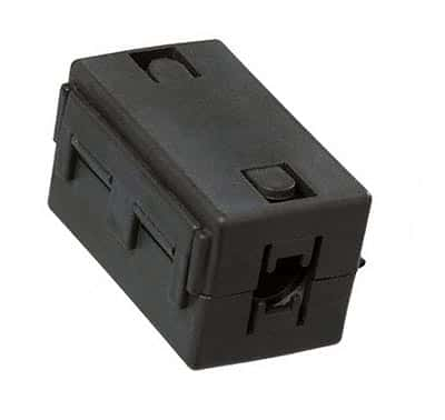
Snap on ferrite for EMI suppression

(Snap on ferrite for EMI suppression)

What Is Electromagnetic Interference (EMI) And How Does It Affect Us?

Electromagnetic interference, abbreviated EMI, is the interference caused by an electromagnetic disturbance affecting the performance of a device, transmission channel, or system. It is also called radio frequency interference, or RFI, when the interference is in the radio frequency spectrum.

All of us encounter EMI in our everyday life. Common examples are:

• Disturbance in the audio/video signals on radio/TV due an aircraft flying at a low altitude

• Noise on microphones from a cell phone handshaking with communication tower to process a call

• A welding machine or a kitchen mixer/grinder generating undesired noise on the radio

• In flights, particularly while taking off or landing, we are required to switch off cell phones since the EMI from an active cell phone interferes with the navigation signals.

EMI is of two types, conducted – in which there is physical contact between the source and the affected circuits, and radiated – which is caused by induction.

The EMI source experiences rapidly changing electrical currents, and may be natural such as lightning, solar flares, or man-made such as switching off or on of heavy electrical loads like motors, lifts, etc. EMI may interrupt, obstruct, or otherwise cause an appliance to under-perform or even sustain damages.

In radio astronomy parlance, EMI is termed radio-frequency interference (RFI), and is a signal within the observed frequency band emanating from other than celestial sources themselves. In radio astronomy, RFI level being much larger than the intended signal, is a major impediment.

Susceptibility to EMI and Mitigation

Analog amplitude modulation or other older, traditional technologies are incapable of differentiating between desired and undesired signals, and hence are more susceptible to in-band EMI. Recent technologies like Wi-Fi are more robust, using error correcting technologies to minimize the impact of EMI.

All integrated circuits are a potential source of EMI, but assume significance only in conjunction with physically larger components such as printed circuit boards, heat sinks, connecting cables, etc. Mitigation techniques include the use of surge arresters or transzorbs (transient absorbers), decoupling capacitors, etc.

Spread-spectrum and frequency-hopping techniques help both analog and digital communication systems to combat EMI. Other solutions like diversity, directional antennae, etc., enable selective reception of the desired signal. Shielding with RF gaskets or conductive copper tapes is often a last option on account of added cost.

RFI detection with software is a modern method to handle in-band RFI. It can detect the interfering signals in time, frequency or time-frequency domains, and ensures that these signals are eliminated from further analysis of the observed data. This technique is useful for radio astronomy studies, but not so effective for EMI from most man-made sources.

EMI is sometimes put to useful purposes as well, such as for modern warfare, where EMI is deliberately generated to cause jamming of enemy radio networks to disable them for strategic advantages.

Regulations to contain EMI

The International Special Committee on Radio Interference (CISPR) created global standards covering recommended emission and immunity limits. These standards led to other regional and national standards such as European Norms (EN). Despite additional costs incurred in some cases to give electronic systems an agreed level of immunity, conforming to these regulations enhances their perceived quality for most applications in the present day environment.