 The highly popular, tiny, single board computer, the Raspberry Pi or RBPi has a row of pins along one of its board edges close to the yellow video out socket. These are its general purpose input/output or GPIO pins and one of its very powerful features.
The RBPi needs these pins to interact with the outside world physically. To simplify things, you can think of them as switches that you can control as inputs or that the RBPi can control as outputs. Of the 26 pins available, nine are for power and ground, while the rest of them (seventeen) are the GPIO pins.
You can set up these pins in different ways to interact with the real world and do fantastic things. It is not strictly necessary that the inputs come only from a physical switch. It might be the input from a sensor, a device or even a signal from another computer, for example. You can use the outputs for anything from turning on an LED to sending data or a signal to another device.
For example, if your RBPi is on a network, you can remotely control devices that are attached to it, while those devices can send data back. The RBPi is ideal for connecting to and controlling physical devices over the internet and that is powerful and exciting thing.
Playing around with the GPIO can be safe and fun, provided you follow some rules and instructions. It is very easy to kill an RBPi if you randomly plug wires and power sources into it – therefore the caution. You could also do a lot of damage if you connect things to your RBPi that use up a lot of power. For example, connecting LEDs to your RBPi is fine, but connecting motors are not. For those newly introduced to the RBPi, using a breakout board such as the Pibrella is a safer alternative than to use the GPIO directly.
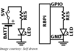
For using the GPIO as an output, the RBPi replaces the power source and a switch in the external circuit. For instance, when an LED is to be lit up, generally a battery is used as a power source and a resistance is necessary to limit the current flow. A switch offers the means to turn the LED on or off. All these are connected in series for the circuit to operate.
To control the LED from an RBPi, you can safely omit the battery and the switch from the circuit. You can individually turn on or off each output pin of the RBPi. Additionally, when the pin is on or digitally HIGH, it outputs +3.3V and when it is off or digitally LOW, it outputs 0V. The next step involves instructing the RBPi when to turn the pin on and when to turn it off.
GPIO inputs on the RBPi require some more work. The RBPi senses an input signal on a pin based on whether there is adequate voltage present. The voltage presented by a sensor must be within levels specified for the RBPi to sense it as digitally HIGH or digitally LOW. Sensing analog or continually varying signals usually needs another interface called ADC or Analog to Digital Converter.