Monthly Archives: May 2015

Using Mechanical Resonance to Improve Machine Performance

Traditionally, most machines typically consist of sets of gears, line shafts and oil baths. Apart from the associated maintenance required to keep the machine in top condition, product changeover can mean physically replacing a gear set or some mechanical cams. Additionally, auxiliary hardware such as compensators may be required to set the motion to its desired pace.

Now, machines driven by distributed servo drives and motors are replacing such traditional machines. The new machines provide several key benefits over their older counterparts. Since each axis in now driven by its own servomotor, there is no necessity for gear sets, oil baths and line shafts. Changing products is much easier and faster, with the motor drives changing the machine speed and switches selecting the required cam profiles. Process control is simpler since servos require only a velocity command to change tension.

However, new technology has its own requirements for achieving optimal performance. Unlike the gear train driven machines, servomotors usually require to be tuned so that they can overcome machine resonance and provide optimum performance. The usual practice follows some key steps.

The first step is to understand the fundamentals. That means analyzing the very nature of the mechanical resonances and finding their natural frequencies. This includes finding out how these resonances arise and how they interact with the several control loops.

Engineers typically use white noise for identifying the resonant frequency as the starting point. This is the primary condition that must be controlled initially through tuning the servo drives. Padding and filtering is often used as primary methods to reduce the impact of the resonant frequency on the control loop.

By adjusting the gains of each of the position control loop, the velocity loop and the current loop, engineers tune each loop such that the actual motion of the machine closely matches the desired motion.

In theory, it is possible to calculate the ideal gain of the control loop based on the inertia and stiffness of the load characteristics and the desired response. However, there can be some factors limiting the value of these gains and the desired bandwidth may not be achieved. For example, a low sampling frequency for the control loop may never allow it to settle on a stable value. However, mechanical resonance plays a more challenging role.

When a mechanical system is excited to its natural frequency, the result is mechanical resonance. The natural frequency causes ringing or vibrations with the minimum stimulus and forms an inherent characteristic of the mechanical system. The effect of resonance is noticeable at certain speeds that are usually related to the natural frequency.

When problems arise due to resonance, the typical response is to change the machine structure to move the natural frequency out of range of the machine operation. The latest converter drives are more effective in overcoming the effects of resonance without investing in additional resources.

Using Fast Fourier Transforms or FFTs, the noise spectrum is displayed as a function of frequency. This plot demonstrates the spike, which is the primary source of the disturbance. Filters are then used to remove the spike and smoothen the output.

Slow Scan Television Camera with the Raspberry Pi

Ham radio operators use their radio equipment and computers to send and receive pictures over wireless. Earlier, most images sent through voice transceivers were low resolution black and white. However, with improvement in technology, nearly all images are of higher resolution and in color. The technique for sending and receiving pictures over radio is called Slow Scan TV. All that is required is a VHF scanner, a computer and a camera. This project replaces the computer with a Raspberry Pi or RBPi, the tiny credit card sized single board computer.

The RBPi with the PiCam forms a wireless camera for transmitting images over very long distances such as tens of kilometers. Finally, the images will be transmitted by ham or amateur radio equipment that uses slow scan television or SSTV over the 2m band (144.5MHz). Here, the RBPi is capable of generating the HF FM signals, and no additional electronics is needed for transmissions at low power. However, with a low pass filter and a single or a two-transistor amplifier, a more powerful transmission can be achieved.

Greater distance coverage is the main advantage of using SSTV over Wi-Fi for transmitting pictures. Using the RBPi as a wireless security camera, you can transmit pictures to distances far beyond the range normally covered by Wi-Fi networks. One of the main requirements is you will need a ham-radio license for using this application.

For transmitting a picture, you will first need to capture it using the PiCam. The program that RBPi uses to do this is named as rapistill. Once the image is captured, it has to be converted to a SSTV sound file. Although there is a program called PySSTV, the conversion rate is very slow and it may take several minutes for converting a single image. However, a simple program implemented in C – PiFm – works very well. The program allows setting the audio sample rate from the command line and converts the picture to an SSTV sound file in just under four seconds.

Although it is customary to transmit the sound file over a radio transmitter, it is much more fun to allow the RBPi to generate its own high frequency signal. Following the Wiki of the Imperial College Robotics, you can turn your RBPi into an FM transmitter. Their code used DMA, but the bandwidth used is very high and the timing for SSTV is not accurate.

In PiFm, bandwidth reduction is very simple. Usually, for FM, the bandwidth is set with the modulation index. This index is the volume of the audio signal modulating the HF carrier. Timing is very essential for SSTV, as a small change in the sampling rate results in slanted images. The timing correction, in the form of a constant, can be set from the command line.

Another requirement when using ham radio for transmitting SSTV signals is that you are required to transmit your call sign in every transmission. This information has to be added to the picture and the RBPi uses imagick from the python image library to accomplish this. Whenever something interesting happens in front of the camera, the RBPi captures the image and sends it over wireless.

What is Emitter-Coupled Logic?

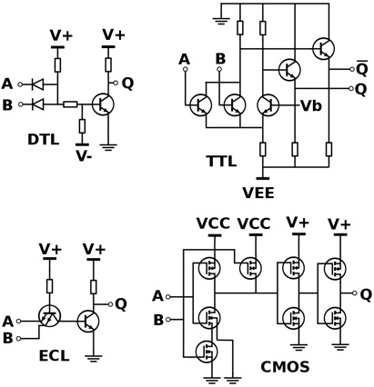
When multiple digital signals have to be combined, engineers use several types of logic gates. One of the most popular and widely used types of logic gates made of transistors is called the Emitter-Coupled Logic or ECL. It makes use of a transistor-based differential amplifier to amplify and combine digital signals. Usually, these circuits or gates, as they are commonly known, have multiple inputs and most are single output. Circuit design ensures that none of the transistors in the gate ever saturates nor are they completely turned off. That means the transistors are always working in their linear active operational region and therefore, do not have to contend with a charge storage time. That makes these gates work at extremely high speeds and this is the main advantage of Emitter-Coupled Logic gates.

For example, consider a three-input OR/NOR gate from the Motorola series of MECL devices. This circuit works on standard voltages of -5.2V (VEE) and ground (VCC). Any unused inputs have to be tied to VEE to prevent erratic behavior. The bias circuit is made up of transistors and associated diodes and resistors (not shown). The circuits are generally packaged as integrated circuits as multiple gates in a single IC. Typically, such ICs include quad 2-input, triple 3-input and dual 4-input gates. Here, the gates differ only in the number of input transistors they are built of, while a single bias circuit suffices for all the gates.

While in operation, a logic output changes its state from a high of -0.75V to a low of -1.60V, a change of only 0.85V. The differential amplifier transistors receive a fixed bias of -1.175V from the internal bias circuit. Now, if all inputs are at -1.6V or tied to the VEE rail, the input transistors are turned off, with the internal differential transistors alone conducting current. This causes the base voltage of the OR output transistor to reduce and its output voltage remains at -1.6V. Simultaneously, since none of the input transistors is affecting the base of the NOR transistor, its output rises to -0.75V, which is the emitter-base voltage VBE of the transistor itself. All transistors in the IC are designed to show a VBE of 0.75V.

As soon as an input rises to -0.75V, that transistor draws emitter current away from the internal differential transistors. This causes the outputs to switch states. Although these circuits work with very small voltage changes, which are typically dictated by the VBE of the internal transistors, the current flowing through various parts of the circuit is of greater importance. This is why Emitter-Coupled Logic has another name – Current Mode Logic or CML. Many other logic types also implement the CML and all of them suffer a major drawback – they draw a great deal of current from the power supply and tend to dissipate heat to a significant amount.

To counter this drawback, other logic systems have evolved, such as TTL and CMOS. For example, high-speed devices such as frequency counters employ ECL only at the input ends of their circuitry, following it up with high-speed CMOS or TTL counters at later stages.

Embedded Pi and Raspberry Pi

To extend the functionality of your tiny single board computer, the credit card sized Raspberry Pi or RBPi you can consider using the Embedded Pi or E-Pi. With E-Pi, your RBPi will be able to interface to Arduino shields even without making use of any Arduino device. For example, the E-Pi RBPi combination can drive a TinkerKit Sensor Shield using a set of actuators/sensors such as LED actuator, button sensor, tilt sensor and a relay actuator.

You may be an intermediate RBPi user or a novice just starting out with the SBC. Using the Embedded Pi will allow you to work with the combination of E-Pi, RBPi and sensor shields for controlling a set of actuators and sensors. In addition, you will learn to write Python code for controlling and detecting the state of the actuators and sensors.

The RBPi can be of either model A or B. For installing the Embedded Pi demo software and the necessary software updates for the RBPi, you will require network connectivity. Since more than two USB devices will be connected, a USB2 hub is recommended. Most likely, you will be connecting the keyboard and mouse through the USB hub along with the WiPi. To link the monitor, use either the HDMI interface or the RCA phono connector, if your monitor accepts composite video.

The Embedded Pi offers an interface platform for connecting the RBPi, Arduino and the embedded 32-bit ARM processor. The Instructions and the E-Pi form a bridge to link the RBPi and the Arduino shields. Physically, this interface takes the form of a cable linking the GPIO connectors on the RBPi and the E-Pi board. On the software side, the linking is achieved by using Rpi.GPIO and WiringPi modules.

The TinkerKit Sensor Shield allows various sensors and actuators to be connected. You can connect them directly to an Arduino or to the E-Pi, without any breadboard in between. There are 12 standard 3-pin connectors on the Sensor Shield. Of them, 10-15 are Analog inputs, 00-05 are the analog outputs. You can drive them with PWM capable outputs or you can configure them as digital inputs.

The TinkerKit uses LED, Relay actuator, button and tilt sensor that are plugged into the 00-05 pins on the Sensor Shield. Both sensors and actuators can be simultaneously used.

To use the E-Pi, connect all the peripherals such as the USB2 hub, mouse, keyboard, WiPi, monitor, etc. into the RBPi and start using the demonstration software. In the next step, connect the RBPi, E-Pi and the Sensor Shield together. Use a flat-flex cable to link the RBPi and the E-Pi together, making sure that the red edge on the flat cable confirms to the proper alignment of the interfaces. On the E-Pi, it is necessary to set jumper JP1, so that its power bus voltage is at 3.3V. Additionally, use only JP3 and not the JP4, such that the E-Pi is configured for the RBPi.

Now connect the LED module with the 3-pin twisted wire cable to the Sensor Shield to its orange sockets – the analog output. Use the epi-leds-rgv1p0p0.py program to run and light up the LED. For further details, see the element-14 site.

Different Types of Digital Logic Gates

digital logic gates explained
In the presence of different digital signals that need to be combined to make a logical decision, engineers use different types of digital logic gates. Usually, these gates have several inputs but a single digital output. Where a larger logic gate function or a sequential or combinational circuit is required, it is usual for individual logic gates to be connected together.

Digital logic gates in standard commercial form are available in two basic forms or families – TTL or Transistor-Transistor Logic and CMOS or Complementary Metal-Oxide-Silicon. An example of the TTL types is the 74xx family and the 4xxx family for the CMOS types. The notation TTL or CMOS is the logic technology that manufacturers use for the Integrated Circuit or IC or chip as commonly known.

The difference in the two families depends on the type of transistors used in making these ICs. While ICs using the TTL logic make use of PNP and NPN type of Bipolar Junction Transistors, the CMOS logic uses JFET or complementary MOSFET type of Field Effect Transistors for their input as well as output circuits.

Apart from the TTL and CMOS technologies, other simpler types of Digital Logic Gates also exist. Some involve the use of diodes, resistors and transistors strung together as RTL or Resistor-Transistor logic gates. Other types are DTL or Diode-Transistor logic and ECL or Emitter-Coupled logic. However, these are far less common compared to the popular TTL and CMOS family, owing to the lower power consumption and heat dissipation of the latter types.

It is usual for ICs to be grouped together into families based on the number of gates or transistors they contain. For example, a single OR gate may be made up of only a few individual transistors, whereas complex micro-controllers have several thousands of individual transistor gates. This leads to integrated circuits being classified as Small Scale Integration or SSI, Medium Scale Integration or MSI, Large Scale Integration or LSI, Very-Large Scale Integration or VLSI, Super-Large Scale Integration or SLSI and Ultra-Large Scale Integration or ULSI. Most complex micro-controllers, video processors, GPUs, CPUs, PICs & FPGAs are examples of ULSI containing several million transistors.

The most modern level of integration, representing the increasing complexity of modern digital circuits, is the Systems-on-Chip or SOC. Here, a single piece of silicon forms the base for individual components such as IO logic, peripherals, memory and the microprocessor. This represents a complete electronic system within the individual single chip.

The Digital Logic Gate forms the basic building block for construction of the entire field of digital electronic circuits and all microprocessor based systems. Digital Logic Gates fundamentally perform logical operations such as AND, OR and NOT on binary numbers represented by digital voltage signals.

The digital logic design recognizes only two voltage levels or states. These are generally referred to as the True, High or Logic “1” and False, Low or Logic “0” states. In Boolean algebra and in standard truth tables, the digits “1” and “0” represent the two states. In terms of voltages, digital logic systems typically use a “Positive Logic”. Here, the level “0” is represented by 0V or ground potential and a higher voltage such as 1.8V or 3.3V or 5.0V represents level “1”.

Use a K-Type Thermocouple with the Raspberry Pi

Whether you are working in a lab, at home, in the office or in the field, occasionally one needs to have the capability to measure the temperature of different sorts of materials such as solids, liquids and chemicals. The temperature range involved may be small or large – its measurement usually requires the use of a thermocouple. This is not very easy to interface, as you need a sensor amplifier that has to measure a very small voltage generated by the thermocouple.

In general, type-K thermocouples are useful in most applications. Extension grade K-type thermocouples are made of Nickel and Aluminum alloy conductors good for measuring a temperature range of 0-200°C. However, other constructions are available that can measure a temperature range of -270 to 1260°C. Thermocouple conductors, when subjected to a temperature gradient, generate a minute amount of voltage – this is called the Seebeck effect. Type-K thermocouples have a nearly linear voltage output versus a temperature gradient. This simplifies interfacing to an electronic circuitry.

The ADS1118 development board from Texas Instruments (TI) is a ready-made platform for using the K-type thermocouple with the Raspberry Pi or RBPi, the tiny credit card sized single board computer. The development board comes with a k-type thermocouple and a high-resolution LCD module. Using eight jumper wires, you can connect this board to the RBPi via the SPI pins on its GPIO. Alternately, use an adapter board to plug in the ADS1118 development board directly to the GPIO pins on the RBPi. Follow the diagram on the left.

The advantage in using an RBPi for interfacing a thermocouple is you can check up on the temperature of your experiment remotely via your smartphone or your PC. The basic idea is to use the RBPi as a web server and to project the temperature measured as a figure on the website that comes up. The following diagram sums up the entire scheme –

The RBPi interfaces with the ADS1118 development board to collect the temperature data via the Serial Peripheral Interface or SPI. It passes this information to the Webserver and application logic. The RBPi also runs a JavaScript in the background for the Webpage content and browser side.

On receiving a request, the web server delivers the webpage containing the temperature data, updating it frequently. This allows remote monitoring of the temperature data from your smartphone or PC. You only have to point your browser to the correct IP address of the webpage.

TI provides a wealth of code for the MSP430 micro-controller on the ADS1118 board. Usually, temperature measurement is a little more than the simple read the ADC value and convert to temperature. It usually involves compensation for the cold junction. For the ADS1118, this means reading another temperature sensor reference on the board. The code does the job of interleaving the readings of the internal sensor and the external thermocouple.

Additionally, the readings need to be corrected for the non-linearity of the thermocouple for accurate interpretation of the thermocouple voltage into temperature. The TI code includes the non-linearity of the thermocouple and translates the ADC value accordingly to actual temperature.

Raspberry Pi Can Open Your Garage Door from Anywhere

Using a Raspberry Pi, you can have a garage door that opens with a command from your smartphone. Additionally, if you are away from home, no matter how far, you can always keep a tab on whether your garage door is shut. The tiny, credit card sized single board computer, the Raspberry Pi or RBPi is used here as a small web server. The page served by this web server will give you a big red button when you access it via your favorite browser.

Pressing the red button will trigger the garage door via a relay. That needs a very simple circuit to be connected to the GPIO pins of the RBPi. The uploaded website will trigger this circuit, which in turn will trigger the relay. The relay contacts will close the circuit to turn the garage motor on and the motor will open the garage door. Another press on the red button will again trigger the connected circuits so that the garage door now closes.

You can use whatever RBPi model available. Additionally, you will need a Wi-Fi adapter, a power supply unit, a 5V relay, a 2GB SD card and some wires. On the SD card, install and optimize the OS Raspbian. This can be the shrunk version of Debian Wheezy – get the image here and follow the installation instructions. Just a tip – use gparted on any Linux computer such as Ubuntu, for format the SD Card to fat32, then dd to write the image on it.

Once the image is installed, plug the SD card in, connect the USB keyboard and hook up the RBPi to a suitable monitor. The first-boot of Wheezy will take you automatically to rasp-config. This tool allows you to stretch the partition and enable ssh. In case you do not want the GUI, use the apt-get command to purge x11-common and autoremove the rest – this will free up some space on the SD card.

Next, use the command line to set up the Wi-Fi so that you will be able to control the RBPi remotely via ssh – use this guide for Wheezy. If you are using the Mode A of RBPi, it has only one USB port. Therefore, for setting up the configuration, you will need your keyboard plugged in. Once the configuration is done, shutdown the RBPi, unplug the keyboard, then plug in the Wi-Fi dongle and reboot the RBPi.

If everything has been done perfectly, the Wi-Fi will be set up and the router will assign your RBPi with an IP address. This will be evident in the boot log of your RBPi if you have a monitor connected to it. Alternately, login to your router and look up the DHCP table. Login to your RBPi through ssh on your Linux PC – type ssh pi@[IP address of your RBPi], with default password as raspberry.

You will need to login, download, compile and install WiringPi – use this guide. This allows complete control of the GPIO pins on the RBPi. Follow the instructions here to control the relay using the RBPi.

How do Piezomotors Work?

Voltage applied to a piezoelectric material causes it to change its shape very minutely. Piezomotors such as Piezo LEGS are ceramic actuators that have four legs as its motors. These are designed cleverly such that the applied voltage can either elongate the legs or bend them sideways. It is also possible to synchronize the movement of each pair of its four legs such that it begins to walk just as an animal would – step by step. While walking, the legs can also stop at any instance on a nanometer level. The driving rod produces direct friction coupling with the legs. That means piezomotors can operate without any mechanical play or backlash. The direct drive, apart from providing full force, also offers power-off locking that does not require any power consumption.

However, the friction coupling between the drive rod and the internal piezo actuator legs does not allow counting the steps or knowing the position of the legs accurately. When they are under constant load, the legs face a certain vibration between the steps. As the load or temperature varies, so do the vibrations. Therefore, separate position sensors are required to know the accurate position of the legs of a piezomotor.

Piezomotors can move extremely slowly. When running in a closed loop system, you can make them achieve a continuous smooth motion at speeds under 1µm/s or 0.001mm/s. Since the speed of a motor depends on its step length and step frequency, a typical linear piezomotor is limited to a maximum speed of 10-15mm/s. In reality, the speed depends on both the external loads and temperature. Therefore, to run the motor at constant speed, you must have a closed loop controller.

Compared to conventional motors, piezomotors are very energy efficient. For example, when in a hold position, piezomotors do not consume any power. They also do not draw peak currents while starting or stopping. Power consumption of such motors is not dependent on inertia. That means the motor will consume the same amount of power under different external torque/load. When operated with a low duty cycle and for point-to-point applications, piezomotors provide excellent battery life.

Just as in regular stepper motors, one can define holding force and stalling force for piezomotors as well. While running, the highest load that the piezomotor can hold dynamically without slipping is called its stalling force. When powered down, the motor is able to hold a load statically and the maximum load that it can statically hold without slipping back is called its holding force. In general, the holding force of a piezomotor is about ten percent higher than its stalling force.

Although the operating principle of a piezomotor is very similar to walking, it can walk with full steps, reduced steps and it can even do micro stepping. Usually, the drive rod or disc will engage with the two or more actuator legs to move them forward and release. Then it will engage with a second set of legs to move them forward. This cycle repeats as long as the motor walks. Therefore, it is always possible to divide the full step into several smaller steps – also called micro stepping.

Why Is Thermally Conducting Paste Used?

No matter how highly polished a surface may seem, when seen under a microscope it will have some irregularities. When two such metal surfaces are put together, air within the irregularities prevents heat from flowing efficiently from one metal to the other. A heat sink is usually placed on a micro-controller to remove the heat generated within the CPU. However, this arrangement will not work in the way desired unless some filler material is used to replace the air in the gaps in the interface between an IC and its heat sink. Such filler materials are usually Thermal Interface Materials or TIMs and generally called as thermally conducting paste.

Thermal pastes are semi-solid materials with very high heat conducting properties. These are placed between two surfaces, usually between a CPU/GPU and its heat sink, to allow better heat conduction between the two. Irregularities on the two surfaces may trap air between them, leading to a loss in the performance of the heat sink, as air is a very poor conductor of heat. TIM, being more than 100 times a better conductor of heat compared to air, improves the performance of the heat sink. However, the heat conducting property of thermal paste is not as good as Aluminum (heat sink material) or Copper (IC material), and a thick layer of TIM might actually hinder the ability of the heat sink to conduct heat properly.

A magnified view of the cross-section of two mating surfaces shows the microscopic imperfections that can trap air as in a pocket. TIM would fill-in these areas, replacing air. If you could have two perfectly smooth and flat surfaces, thermal paste would not be required to aid in heat transfer. However, that being impossible to achieve, thermal paste is necessary to improve the flow of heat. Depending on the application, you could use one of three types of thermal pastes – Silicon based, Ceramic based or Metal based.

Silicon based TIMs are generally used in cooling kits. These are commonly known as thermal pads and stock heat sinks use them freely. However, other pastes have better heat conducting properties.

When you need a paste that can also isolate electrically – Ceramic-based TIMs are hard to beat. They consist of a thermally conductive paste with plenty of tiny ceramic particles, which prevent flow of electricity. Although not as good as the Metal based TIMs, the difference is only minimal.

Metal-based TIMs are the most popular. These have the best performance characteristics, which comes from the innumerable tiny metal particles present in the high thermally conducting paste. However, this paste has a disadvantage that it can also conduct electricity.

Apart from the above three types of TIMs, there are also thermal epoxies. Although these function in a manner similar to the thermal pastes described, they possess an additional property – they can attach the heat sink permanently. Therefore, thermal epoxies must not be used when you need to get the heat sink off an IC. In case you have to separate a heat sink from an IC bonded together with thermal epoxy, the best procedure is to place the assembly in a freezer. The cold makes the epoxy brittle and it comes off easily.

Demystifying Power over Ethernet

Power over Ethernet or POE is an upcoming technology and most information available on the subject is either outdated or creates a lot of conflict. That puts off people wanting to use this new technology. Some misconceptions common to POE is discussed here.

POE leads to compatibility problems. In the early days of POE, several proprietary and home-brewed schemes were used to transfer power over networking cables. However, the standard IEEE 802.3af is now universally adopted for POE. That means compatibility between all modern equipment using POE is assured.

To use POE, one needs electrical knowhow. That was true of early implementation involving careful design. However, with IEEE802.3af, the design of POE ensures reliable operation in all configurations that is possible with the regular implementation of Ethernet. When the user has set up the network to work as normal, the equipment takes automatic care of delivery of power.

Special wiring is required for POE. This is not true. You can use the same cabling as used for regular Ethernet networks – RJ45 style of connectors with Cat6 and Cat 5e cabling. Both regular as well as POE-enabled local area networks can use the same connectors and wiring.

POE forces power into the device. This is a common misconception. Usually, manufacturers quote the maximum power ratings and the device draws only the power it needs. For example, if you plug in a 5W device into a socket capable of delivering 15W maximum, the power consumption is only 5W and there is no loss of 10W somewhere. Any electrical load will draw only the power it uses and no more.

The POE standard 802.3af is meant for network devices that draw around 13W of electrical power. However, there are devices in the market with POE that require a little more than 13W. Usually, these devices are proprietary and such high-power POE systems are not always compatible with devices complying with 802.3af POE.

The latest POE standard deals with such devices. This new standard IEEE 802.3at is called POE Plus and it handles double the electrical power – devices that can handle up to 25.5W.

Injectors and switches compatible to POE Plus can recognize any normal POE devices plugged into them and enable them as normal. Conversely, any POE Plus powered device plugged into POE injectors or switches are designed to restrict the amount of power they use.

The new standard 802.3at has scope for power budgeting. POE Plus devices can communicate with each other and simultaneously negotiate the allowance of electrical power. That means you can POE-power a more complete range of network equipment. This can include heaters and blowers, along with multichannel wireless access points.

However, both standards 802.3af and 802.3at coexist with each other and POE Plus does not replace POE. There are still many users of 802.3af for powering Power over Ethernet devices.

Most network cables utilizing Cat 6 or Cat 5e are made of eight wires arranged as four twisted pairs. Ethernet cables such as 10 and 100BASE-T use two of these pairs as data pairs for sending information. The balance two pairs, known as the spare pairs, remain unused. POE uses either the two data pairs or the two unused pairs at 48V to transfer power.