Monthly Archives: March 2015

What are WAN, LAN and DNS?

For those setting up a network at home to interconnect computers, it is important to know some technical jargon used in this field. Knowing the basics of home-networking makes it easier to read up and understand how actually computers talk to each other. Broadly speaking, computer communication is achieved in two ways – with wired networks and wireless networks. In this article, we will discuss wired networking.

Wired networking in the home refers to a number of devices connected together using a network of cables. Usually, this is accomplished with the help of a router, a central device, into which you plug in all the other devices using networking cables. The other end of the cable goes into a network port on the other devices. For this, all the other devices must have an individual networking port built into them. For all the end-devices that you want to connect to the router, you will need a free port on the router and a networking cable.

When you connect end-devices to a router, you are essentially creating a Local Area Network or LAN. A typical router has four LAN ports. Therefore, straight out of the box, it is able to host a network of four networking devices. If you want to add more to have a larger network, you must use a hub or a switch to add more LAN ports to your router. The router will identify all the end-devices connected to it with individual IP addresses. In general, a home router is able to handle 250 networking devices in total.

To allow the end-devices access to the Internet, a home router usually has a single WAN port, or Wide Area Network port. Some business routers sport two WAN ports, allowing users to connect to two separate Internet services. Physical separation and a different color distinguish a WAN port from the LAN ports. Via the WAN port, you can connect the router to an Internet source such as a broadband modem. You can also buy a combined router, which is a DSL/Cable modem and an Access Point (with a wireless router) bundled into a single package. in such a scenario, a telephone port (or a coaxial port) and a USB port typically replace the single WAN port, allowing connection of a telephone line, a cable and/or a wireless USB data card as Internet sources.

We name a website with a unique domain and host name to identify it. This is similar to the street number and the apartment name that identifies an address in real life. Since computers understand only IP addresses, DNS or Dynamic Name Servers translate the domain and host names to IP addresses transparently.

With DNS, a distributed database stores the name and address information of all the public hosts on the Internet. A hierarchy of special database servers stores this distributed database. Typing a web address into a Web-browser, which is the client, results in requests from a DNS resolver from the network operating system to the DNS server for determining the server’s IP address. DNS servers typically work in a hierarchy and, after locating the IP address, send it back to the resolver, thus completing the request over Internet Protocol.

How to Select Voltage References

how to select voltage referencesSensing applications use Analog to Digital Converters and Digital to Analog Converters and the accuracy of their readings depends on the voltage reference used. Most often the voltage reference used are very simple components with only two or three pins. However, the performance of these references depends on several parameters and careful attention is necessary when selecting the proper one. Typically, applications use either a shunt or a series voltage reference.

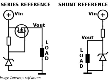
A series voltage reference is basically a high precision, low-current linear regulator. The load current comes through a series transistor positioned between the input voltage and an internal reference voltage. For the shunt voltage reference, a transistor placed parallel to the load shunts excess current to ground. As the series reference has to supply only the required load current, the shunt reference dissipates more power. The bias current of a shunt reference has to be greater than or equal to the maximum load current plus the minimum operating current of its internal reference.

In general, shunt references offer the user greater flexibility in handling higher input voltages and in creating floating or negative references. They also provide better power supply rejection but consume higher power. On the other hand, series references dissipate lower power and perform better for high-precision applications. The typical way of depicting the use of a shunt reference is by showing the symbol of a Zener diode.

Drift or variation of the reference voltage over temperature is a very important factor and has the units of parts-per-million per degree Celsius or ppm/°C. Most monolithic references use the bandgap reference as their base. Special circuitry is required to maintain drifts lower than 20 ppm/°C with the additional circuitry providing some form of curvature correction. Other types of references use a buried Zener diode voltage combined with the base-to-emitter voltage of a bipolar transistor to provide a stable reference voltage of about 7V. Both types have similar drift characteristics, but buried Zener types offer better noise performance.

All voltage references generate internal noise producing a dynamic error degrading the signal to noise ratio of a data converter. Device datasheets typically provide specifications separately for low and for high frequency noise in addition to the broadband noise in rms microvolts over the 10 Hz to 10 KHz bandwidth. You can reduce the broadband noise by adding a bypass capacitor.

Thermal cycling or change in temperature causes references to show thermal hysteresis. This appears as a shift in the reference voltage. Manufacturers define a thermal cycle as an excursion from room temperature to a minimum and a maximum temperature with a return to the room temperature. This is important as the reference may have to be soldered and this can induce shifts from the desired reference voltage.

Continuous operation may cause long-term stability issues resulting in a typical shift in the reference voltage. Manufacturers usually state the shift after six weeks or 1000 hours of continuous use. Since long-term stability is typically related logarithmically to time, the shift in reference voltage in the first 1000 hours provides a rough idea of the stability of the voltage reference over its life.

Raspberry Pi Lights up a 64×32 RGB LED Matrix

When you want to make a video wall such as those found on the sides of buses and bus stops in New York, you need a panel with a matrix of LEDs. These are very handy for displaying short video clips or animation. Adafruit has quite a few of them in different matrix sizes such as 8×8, 8×32, 16×24, 32×32 and 64×32. The last one is available in pitches of 3, 4, 5 and 6 mm.

LEDs on the panel are placed close together in a 3 mm pitch, so that you can appreciate it from up close. With the matrix being made of bright RGB LEDs, you have a 160-degree wide-angle view and the panel looks great both in either ambient light and indoors. You can use panels with a larger pitch if you want it to be read from still farther.

In the matrix on the panel there are 2048 gleaming RGB LEDs arranged in a grid of 64×32 in front. The backside of the panel sports a pair of IDC connectors – one of them is for input and the other for output. You can drive the display with a 1:16 scan ratio when the two connectors are chained together. For this, you need 12 numbers of 16-bit latches.

Along with each panel, Adafruit provides an IDC cable, a plug-in power cable, four mounting screws and mini-magnets (for mounting quickly on a magnetic base). You will have to buy the regulated 5V power supply unit separately. The panel consumes about 4A. The panels need 13 digital pins of which 6 bits are required for data and 7 bits for control. That makes the panels perfect for being driven with the tiny, inexpensive, credit card sized SBC, the Raspberry Pi or RBPi.

You cannot drive these displays by FPGAs or any other processors using high speed, as there is no PWM control built into the panel. Instead, you need to refresh the display manually by redrawing the screen repeatedly. For example, for displaying a 4096 color image (12-bits), you will require about 3200 bytes of RAM for buffering and the process will take up about 40% of CPU time. Adafruit provides support with complete wiring diagrams and library code for drawing pixels, circles, rectangles, lines and text.

An RBPi cannot directly drive the RGB LED display matrix directly. The GPIO pins on the RBPi cannot provide the necessary drive. Moreover, signals from the RBPi will have to be level shifted as the panel works off 5V, as compared to the 3.3V for the RBPi. Adafruit has a drive board – the RGB Matrix Hat. This sits on the RBPi and makes it easy for the RBPi to control the RGB matrix for creating a colorful scrolling display.

It is very simple to link up the RGB Matrix HAT with the panel on one side and the RBPi on the other. Plug in the HAT on to the RBPi, plug in the IDC cable and turn on the respective power supplies. Now, run the Python code from Adafruit. The 5V, 4A wall adapter plugs into the HAT, which protects against under, over and negative voltages to the display.

Raspberry Pi accessories from Microstack

If you are looking for accessories for your tiny, credit card sized single board computer, the Raspberry Pi or RBPi, you now have a series of them from the distributer element14. This Microstack range of accessories allows all levels of users to create and prototype physical devices simply and quickly. Most popular among the Microstack accessories are the GPS positioning and accelerometer.

Microstack claims that its modules are the “building blocks for the Internet of Things for All”. The original designers of PiFace Digital and PiFace Control and Display accessories for the RBPi have come together to create Microstack. In fact, building on PiFace, Microstack now offers several types of connected-device possibilities for the RBPi.

Microstack offers a family of stacking accessory boards that a compact and reusable. They offer a common form factor, interface connections and software. All the accessories for the RBPi are built on a platform-specific baseboard called the adapter board.

The GPS module from Microstack is a simple and easy plug-and-play solution. You can use this module for projects requiring GPS positioning for creating geo-location awareness. The GPS module has several worthwhile features. Not only can the module log data in its standalone mode, it allows the RBPi to keep time in a highly accurate and globally synchronized manner. The Microstack GPS module is one of the most complete and advanced modules and it sports an embedded high sensitivity 15×15 mm internal patch antenna with an external socket.

The antenna switching function is automatic as the GPS module has antenna detection feature along with short circuit protection. For better sensitivity, the module has a built-in LNA. The advanced AGPS technology works with an intelligent controller of periodic mode that does not require any external memory. Microstack has provided LOCUS as an innate logger solution that works independently without host and external flash. The GPS module comes with anti-jamming features that sports Multi-tone Active Interference Canceller with 66 acquisition channels and 22 tracking channels. You can combine it with other Microstack add-ons to provide radio links for supporting remote telemetry.

The Accelerometer module from Microstack is also a simple plug-and-play device for the RBPi. It is useful where measuring acceleration is necessary for projects such as tracking and motion, game and tilt sensors and robotics. The module is based on MMA84910, a simple, low power, three-axis low-g accelerometer that offers multi-range 14-bit at +/- 8g resolution.

With a 1.95-3.6 V supply voltage range, the Accelerometer module consumes only 400 nA per Hz, but provides data at ultra-high speeds in about 700µS. Its 14-bit digital output has a sensitivity of 1 mg/LSB with a +/- 8g full-scale range. The Microstack framework compatible accelerometer module has 45° tilt outputs for its three axes and you can link it to your RBPi with the I2C interface.

You can use the Microstack modules as standalone or integrate them into full custom PCBs. Therefore, the modules provide a solution right from prototyping to production. These modules offer powerful building blocks that cut down on the development time with support software and easy installation.

Common Mode Signals and the Twisted Pair

People dealing with networking and instrumentation would have often come across the term “twisted pair”. This usually consists of two insulated wires twisted tightly together and is the most common method used to prevent noise on the wires from being carried into a device. This applies to most cables carrying signals related to communication on RS-485, RS-422, computer-network, video, audio and telephones systems. In technical terms, these signals are known as Common Mode Signals.

When you have a local common or ground, any signal with this as the reference and appearing on both the lines of a two-wire cable, with equal amplitude and in-phase, is called a Common Mode Signal. Therefore, if one of the wires is tied to the local common, the common mode signal will be non-existent. There are three ways such signals can arise – radiated signals can couple equally with both lines, the driver circuit may have an offset from the signal common or a ground differential may exist between the receiving and transmitting locations.

For an example, consider the three-phase Y-distribution lines of the AC power system. The neutral current of such a system flows through the earth and this can be 10-70% of the total neutral current flowing in the primary circuit. Ground differentials vary between locations and can be as much as several volts to several tens of volts. This differential can cause the three phases to be unbalanced by 0.2VRMS to 5VRMS.

Noise signals may appear in a cable for various reasons. For example, noise can be capacitive coupled from nearby electric fields, inductively from local magnetic fields, electromagnetically from radio signals or conductively from circuit path leakages. However, when you have a twisted pair line, it intercepts the coupled signal equally, making the incident signals appear only as common mode signals. You have a balanced twisted pair line if there is identical impedance from each line to the local common.

When driving audio signals across a pair of twisted wires, either wire has the same chance of being coupled to some unwanted signal or noise as its twisted partner. That means this common mode signal or unwanted signal appears equally on both wires. The audio circuitry is designed to reject this type of common mode signal and this characteristic is known as its CMRR or Common Mode Rejection Ratio, expressed in dB. Achieving circuit balancing is carried out in two ways – most commonly through impedance balancing and through differential balancing.

With impedance balancing, you can achieve better common mode signal (noise) rejection, as there is a balanced connection to ground. The simplest but most effective way is to use two matched resistors from each line to the common ground. The cable wires must also have the same diameter and resistance for the balancing to be most effective.

In differential balancing, the source equipment transmits the normal signal through one of the conductors of the twisted pair and a polarity-inverted signal through the other. Such differentially balanced or symmetrical lines offer the highest common mode rejection ratios, even though the principle remains the same as that of impedance balancing.

Raspberry Pi Handles Extreme Machines

In general, we know of two types of internal combustion engines used in vehicles – Gasoline and Diesel. The gasoline engine relies on electric sparks for igniting its air-fuel mixture, while the diesel engine relies on heat and compression to do the same. Introduction of new types of renewable fuels such as biodiesel, bioethanol and Hydrogen are leading to newer types of internal combustion engines such as those utilizing HCCI or Homogeneous Charge Compression Ignition.

HCCI uses a type of internal combustion mechanism where fuel is mixed with an oxidizer such as air and the mixture is compressed until it ignites on its own. The exothermic reaction thus created by the combustion of the air-fuel mixture releases its chemical energy and transforms it into a sensible form that the engine can use for generating work and heat.

Extreme machines use HCCI as this method combines the characteristics of conventional diesel and gasoline engines. Diesel engines use CI or compression ignition with SC or stratified charge – abbreviated as SCCI. Gasoline engines use SI or spark ignition with HC or homogeneous charge – abbreviated as HCSI.

An HCCI engine injects fuel during its intake stroke. This is similar to what happens in an HCSI engine. However, unlike the HCSI engine using an electric discharge to ignite the mixture, the HCCI engine compresses the mixture to raise its temperature and density, until the entire mixture reacts completely. This is different from the functioning of the SCCI engine.

An SCCI engine also increases the density and temperature during compression. However, the difference is that it injects fuel only after the compression stroke is completed. This leads to combustion occurring at the boundary of the air-fuel mixture, resulting in higher emissions. Since the method allows a leaner and higher compression burn, SCCI engines are more efficient.

Controlling extreme machines such as HCCI requires precision and a physical understanding of the ignition process. With proper control, such as with a microprocessor, HCCI engines can achieve efficiencies typical of diesel engines and emissions such as gasoline engines do.

Adam Vaughan has developed an adaptive algorithm for controlling extreme machines such as those using the homogeneous charge compression ignition His algorithm runs on the tiny, credit card sized single board computer, the Raspberry Pi or RBPi. The algorithm learns and adapts to the HCCI mechanism in real time.

The near-chaotic combustion process in an HCCI engine is hard to predict. Adam’s algorithm requires roughly 240,000 samples per second of data to predict how the engine is likely to behave. This is very close to real-time monitoring – the latency or lag approaches a mere 300µS.

Data sent to the RBPi includes pressure from each cylinder of the engine, the angle of the crank rod and the heat released. RBPi records this data and uses it to control the engine in real time over a CAN or Controller Area Network. With the real-time control provided by his algorithm on the RBPi, Adam is able to improve the efficiency of the engine and reduce its carbon dioxide emissions drastically. Watch RBPi controlling the extreme engine here and you can read about Adam’s algorithm here.

Raspberry Pi drives photon elephant

You are looking for the best way to control your 3D printer and turn it into a smartprinter. If you are not averse to using a browser-based control panel that will allow you to stream from a webcam, start, pause and resume print jobs while slicing your STL files, you may consider the Photon Elephant.

The Photon Elephant uses the tiny, low-cost, credit card sized, single board computer – the Raspberry Pi or RBPi – to drive the motor controllers of your printer. A conventional SDK or Software Development Kit uses the GPIO pins of the RBPi for the controls. This is all open-source, which means you can tinker with it to your heart’s content. For example, you may want more than what the standard 5-motor controller has to offer. With the Photon Elephant, you can have more time innovating rather than figuring out what makes the firmware tick.

Photon Elephant provides you a bunch of software and hardware based on the RBPi that controls your 3D printer. Printers available in the market typically use an Arduino, without an operating system, to manage the sensors and motors, while the RBPi is used to send it commands. Photon Elephant puts the power of Linux directly into your printer by eliminating the Arduino.

Anyone can build on the simple but powerful Photon Elephant platform. The platform makes it easier to create new and exciting types of 3D printers. Available open source solutions for controlling 3D platforms tend to be out of date and tedious. With the Photon Elephant, the next generation of 3D printers will be more flexible to control.

Entrepreneurs, students, makers and hackers anyone can easily use the Photon Elephant. It handles the entire stack and controls everything from sensors, motors and the User Interface. If you are looking for the simplest solution for getting your printer up and running, Photon Elephant is for you. Additionally, with the Photon Elephant SDK, you have the easiest platform you can build upon.

There is no firmware to be flashed. Use the pre-programmed image on the SD card and plug it in to fire up your RBPi. All you require to do is to connect any compatible printer to the Photon Elephant companion board and you can start using your printer. All the different firmware such as the slicer and printer managers talk seamlessly to one another. Therefore, you simply have to open up a browser on any device and start using the printer over Wi-Fi.

The 3D printing industry is moving forward very rapidly and printers become outdated very quickly. Currently, Photon Elephant is able to support Cartesian RepRap style of printers only. Very soon, Delta printers will also be supported. The SDK is flexible to take on almost any printer methodology.

Flexibility is extremely desirable considering how difficult it is to predict the direction the 3D industry may be taking. There is no sense in spending time in modifying the firmware directly on a chipset as it may become useless by tomorrow. The flexibility of the Photon Elephant SDK helps the user keep up with the industry, as it is very easy to add newer features to the current design

How does an Android process sense motion?

The Android 4.4 Operating System from Google is able to track your motion in real-time. You can test this with the Google-map application when traveling – your current position as shown on the map will shift as you move. Although this was feature available earlier as well, Google has mandated that 4.4 version onwards, Android will be using this function in the background while it has turned the application processor off. Google has introduced this change to save battery life.

To comply with this mandate, manufacturers will now have to offload this function from the application processor and transfer it to a sensor hub. In anticipation of this mandate from Google, InvenSense has already transferred those functions into their patented DMP or Digital Motion Processor, which they have announced as their six-axis MEMS combo processor for an accelerometer and a gyroscope. Therefore, smart sensors will be providing the real-time contextual awareness functions in the background of your smartphone, while its screen is switched off.

This can be done in one of two ways. One of them may be to allow several new sensor functions to be run in a sensor hub. However, this has the disadvantage of adding cost to the product. A much better way, followed by InvenSense, is to include the processing within the sensor itself, which means smartening up the sensors. The MPU-8515 is a six-axis digital motion processor developed by InvenSense for this purpose.

Inside the MPU-6515, there is a three-axis gyroscope along with a three-axis accelerometer housed within the same package. With an enhanced version of their DMP built into their MPU, InvenSense is able to handle the specific functions that the Android operating system mandates running external to the application processor. With the MPU-6515, sensors can remain on for more time and supply more real-time data for location and context awareness yet reduce battery consumption.

In practice, the Android operating system shuts down the application processor when there is no activity input from the screen. It wakes up only when it receives a significant motion interrupt while rejecting false triggers to switch the application processor back on. Significant motions include pedometric functions such as detecting and counting steps while running in the background.

Processing information accurately when the application processor is turned off involves inertial location tracking. That requires processing rotation vectors involving six axes. The MPU-6515 does this by amalgamating the outputs of three axes from the gyroscope and three axes from the accelerometer sensors and buffering them periodically between the significant motion interrupts using a new batch mode.

The MPU-6515 can work in both modes – with a hub or in a hub less mode. This additional functionality is helpful for situations where the Android operating system has turned off both the application processor and the hub. Using this combo gyroscope and accelerometer chip with enhanced digital motion processor, InvenSense has been able to enhance its handling of contextual awareness for the Android operating system.

Manufacturers can easily use the MPU-6515, measuring a mere 3x3x0.9 mm, in smartphones, wearables, tablets and in devices for Internet of Things. Those using the earlier device from InvenSense, the MPU-6500 can easily replace the older chip as both are pin-compatible.

Why is Li-Fi better than Wi-Fi?

Imagine wandering through an art gallery with your PDA. As you reach an interesting canvas, your PDA starts downloading information about the painting. When you move to another, your PDA displays content relative to the current piece of art. This is called content fencing – tailoring information to specific locations so that users receive information relevant to their current location.

Content fencing is impossible to achieve with Wi-Fi – radio waves have a far greater spreading power. However, this is eminently possible if electromagnetic waves of very short wavelength – such as optical beams – are used. We already have the necessary technology with us and it only requires converting LED bulbs into wireless access points as an equivalent of a wireless network. This is LI-Fi, allowing you to move between light sources for effectively remaining connected. At present, Li-Fi is only a complementary technology compared to Wi-Fi, but its potential benefits over Wi-Fi are huge.

Visible light spectrum has a huge bandwidth compared to the RF spectrum – in excess of 10,000 times. Moreover, visible light spectrum is unlicensed and free to use. RF tends to spread out over a large area causing interference, whereas, visible light can illuminate a tight area and can be well contained. This allows Li-Fi to attain over a thousand times the data density than Wi-Fi can achieve.

Low interference means more data can be transferred. Therefore, Li-Fi achieves very high data rates and devices using Li-Fi can have high bandwidths along with high intensity optical output. With illumination infrastructure already available in most places, it is relatively easy to plan for introduction or expansion of Li-Fi capacity with good signal strength.

The presence of illumination infrastructure also means negligible additional power requirements for Li-Fi, more so because LED illumination is inherently efficient. In comparison, radio technology requires additional components and energy to implement. Li-Fi works very well in water, but it is extremely difficult to implement and operate Wi-Fi underwater.

Even today, there is a raging debate about whether RF transmission is safe for life on Earth. Visible light does not court such controversy regarding health and safety, as it is the Sun’s rays that sustain life on Earth. Moreover, in certain environments, radio frequencies are considered dangerous as they can interfere with electronic circuitry. That is why people are asked to switch off their phones in flight.

The closely defined illumination area makes Li-Fi very difficult to eavesdrop. Unlike Wi-Fi that spreads its signals all over, even passing through walls, Li-Fi signals are confined to a specifically defined area. This makes Li-Fi far more secure as compared to Wi-Fi. Moreover, data flow in Li-Fi technology can be visibly directed according to requirement. You only need to point one device towards another to make them communicate. That makes it unnecessary to add a layer of security such as pairing, as is required for a Bluetooth connection.

Considering that LEDs operate more than 50,000 hours, it is necessary for manufacturers to add new services to the light they sell. Li-Fi offers massive new opportunities and myriad of different applications for the future communications market.

Connecting to the web via LEDs: Li-Fi

Connecting to the Internet is best done through copper wire or high-speed wireless connections. Not many are aware of an additional method – using light beams. This is accomplished not by the usual optical fiber stuff, but by using LEDs. Communication with lights is nothing new – it has been done before. The Scottish scientist, Sir Alexander Graham Bell had invented an arsenal of instruments for communication and these included Photophones.

The first instruments to use light for communication were Photophones. Now, after about 110 years after the invention of photophones and their fading into history, Professor Harald Haas is conducting experiments in wireless communication using light-centric technology. At the University of Edinburgh in Scotland, Professor Haas is using the Alexander Graham Bell building for his experiments.

Professor Haas demonstrated his vision for the future of wireless communication way back in 2011. He was using something as simple as LED bulbs for his experiments. This is also the time when the term Li-Fi was coined. Li-Fi is now used to describe bidirectional networked wireless communication using visible light as a replacement for traditional radio frequencies.

With people implementing the Internet of Things in full swing, it will not be very long before there is a spectrum crunch for the radio frequencies. In this context, light modulation and enabling connectivity through simple LED bulbs will have huge ramifications. Li-Fi can allow you to connect to the Internet as soon as you are within the range of an LED beam. Even your car headlights can be used to transmit data.

Professor Haas is working towards PureLiFi, which can offset the global struggle for the vanishing wireless capacity. PureLiFi is striving to develop and drive technology suitable for secure, reliable and high-speed communication networks. This will help to integrate data and lighting utility infrastructure seamlessly while reducing energy consumptions significantly.

One of the most interesting features of Li-Fi is its security over the conventional networking methods. Although Li-Fi is not yet available on the Internet marketing websites, companies from the security-focused fraternity are highly interested parties. That is because prying eyes of third-parties find Li-Fi significantly harder to infiltrate compared to other current networking technologies.

Li-Fi signals travel over narrowly focused beams and they cannot penetrate walls. Additionally, with LED lights, you have natural light beams; therefore, the uplink and downlink channels can be separated leading to increased security. For example, if you are browsing using two-channel Li-Fi, both beams will have to be intercepted for someone to infiltrate into your computer, provided they first gain entry into the same room as you are in.

In practice, Li-Fi networks use a desktop photosensitive unit to communicate with an off-the-shelf unmodified light fixture using infrared LEDs for its uplink and downlink channels. Within a range of about three meters, you can have uplink and downlink channels delivering a typical capacity of 5Mbps. With Li-Fi, it is possible to achieve speeds as high as 10Gbps as well. As an additional benefit, your workspace remains well lit.

Li-Fi allows you to have your content tailored before delivery. Within a single room such as in an exhibition, you could wander through various beams to pick up information relevant to your current location.