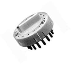
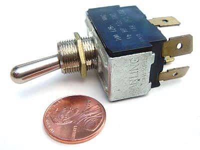
Category Archives: Switches

Using Hall-Effect Type Sensors Effectively

We are familiar with appliances such as wine coolers, freezers, and refrigerators. They keep out beverages and food cold, extending their useful life. Most often, these appliances have lights that illuminate the insides when the user opens their doors. Since the lights only need to be on when the user opens the door, usually, the designer of such appliances place a sensor to detect the opening and closing of the door.

A sensor of the Hall-effect type can detect the position of the door. In refrigerators, the position of the sensor is within the frame, while a permanent magnet is placed on the door directly opposite the Hall-effect type sensor. For refrigerators with multiple doors, each door needs a magnet and for the detection, each magnet must have a corresponding sensor placed in the frame. The adjustment of proximity of each Hall-effect type sensor and magnet pair is such that the Hall-effect type sensor detects the magnet only as the door closes completely.

An electronic control unit inside the electronics assembly of the refrigerator monitors the output from the Hall-effect type sensors and turns the lights on or off as necessary. Hall-effect type sensors can detect a variety of proximity- and position-sensing applications such as when there is a need to discover the proximity of a moving part relative to a sensor placed in a fixed location.

For instance, Hall-effect type sensors can help to stop the motor opening or closing a garage door once the door has reached its desired position. Typically, this needs a system of two Hall-effect type sensors to detect the two dominant positions of the door—open or closed. Each sensor also needs a corresponding magnet to trigger it.

The position of one of the magnets on the drive chain of the garage door opener places it directly next to the sensor that detects a closed door. The position of the other magnet, also on the drive chain, is such that the drive chain brings it next to the other Hall-effect type sensor as the door opens completely.

Hall-effect type sensors are preferable to other sensors such as reed relays, as the former has no moving electrical contacts, resulting in long life and improved reliability. Other applications that use Hall-effect type sensors effectively are vending machines, security locks on doors, vacuum cleaners, washing machines, dishwashers, and similar applications requiring door- and lid-position sensing.

A flow switch is another application that benefits from the use of a Hall-effect type sensor, which detects the motion of a piston, paddle wheel, or a valve fitted with a permanent magnet. For instance, this arrangement suits tankless water heater units, where the flow sensor has a permanent magnet fixed to a piston. The increasing presence of water pressure in the system moves the piston and its associated magnet near to a permanently positioned Hall-effect type sensor. This causes the output of the Hall-effect type sensor to change and it signals the presence of flowing water.

Similarly, a turbine can have a magnet attached to its blades. As the blades rotate, the magnet passes by a fixed Hall-effect type sensor. The speed at which the blades rotate is proportional to the fluid flowing through the turbine.

Advanced Applications Need Alternate Switch Technologies

Although conventional reed switches have been in use for their excellent properties, their large size makes them difficult to integrate in advanced applications. Most equipment now use miniature components and manufacturers have found a way to reduce the size of reed switches to match. They now use HARM MEMS or High Aspect Ratio Microfabrication MEMS technology to make miniature reed switches, keeping all their desirable properties intact.

Reed switches are popular because they do not require power to operate, they offer milliohms of ON resistance, and tera-ohms of insulation when OFF. They are immune to ESD or electrostatic discharge. Moreover, they require very little additional circuitry to operate and hence, take up very little real estate on the printed circuit board. Some advanced applications where the alternate HARM MEMS reed switches are useful are as follows.

Small Portable Hearing Aids

The baby-boomer market is increasingly in need of small portable medical devices such as hearing aids or hearing assistance devices. HARM MEMS switches are ideal for the control functions in these devices. As the user preference for small, almost unnoticeable hearing aids grows, the ever-shrinking devices are making increasing use of the tiny magnetically operated switches for functions such as Telecoil operation and program switching. As these switches need no power to operate, the once bulky behind-the-ear hearing aids are disappearing into the ear canal itself. Since batteries have also shrunk, the zero power operation of the microfabrication reed switches is a boon for the user.

Endoscopes the Size of Capsules

No one forgets the trauma of getting an endoscope done to know what is wrong within his or her gastrointestinal tract. However, that might soon be outdated, as HARM MEMS can shrink the endoscope down to the size of a capsule, which the patient swallows. As the pill shaped endoscope passes down the gastrointestinal tract, its one or more video cameras capture images lit by its white LED headlamps, also a part of the pill.

As the device is small enough to be swallowed easily, the capsule endoscope has electronic circuitry that is highly miniaturized, so that it can reach where conventional endoscopes or colonoscopes cannot. The tiny pill requires a mechanism to allow it to start functioning just before it is swallowed. In addition, there must be no drain from the tiny batteries when the device is in storage. Active switches are not helpful here, as they draw current even when inactive and hence reduce the shelf life. HARM MEMS switches are the best fit here because of their tiny size and zero power consumption.

Insulin Delivery Pumps

All over the world, diabetes is increasingly affecting people of all ages. In the most severe form of this disease, insulin must be administered multiple times daily to the body. There are two ways to do this – either by multiple daily syringe injections or via insulin pumps. The pumps generally contain a disposable insulin reservoir. The pump unit must reliably detect this reservoir. Modern insulin pumps are small credit card sized and contain a HARM MEMS reed switch, which is activated by a magnet attached to the reservoir.

Integrating Piezoelectric Flexure Actuators

The familiar reed switch comes with a unique set of properties. These include ON resistance of the order of milliohms, OFF resistance of the order of tera-ohms, total immunity to ESD or electrostatic discharge, hot switching capability of about one watt, and almost zero power operation. However, as all electronic components are shrinking to surface mount sizes of 0402, 0201 and even to 01005 (0.4 x 0.2 mm), the large size of the reed switch is anachronistic. Since 70 years of its invention, the conventional reed switch has been steadily shrinking. What began with a 50 mm long glass tube in 1938 has come down to about 5 mm today.

However, even after a sort of following Moore’s law of ever-shrinking transistor size on integrated circuits, reed switches have now reached a brick wall. The fundamental limitations of physics and manufacturing are preventing the conventional reed switches from going below the 5 mm size. Now, a new technology promises to break this barrier of 5 mm size, while retaining all the desirable properties of the reed switch. Manufacturers are using HARM, or High-Aspect Ratio Microfabrication MEMS technology. For instance, reed switches such as the RedRock RS-A-2515 piezoelectric flexure actuators from Coto Technology is based on this technology.

Alternatives to reed switches also exist. For instance, there are Hall Effect switches, AMR or Anisotropic MagnetoResistive switches, and GMR or Giant MagnetoResistive switches in the market. However, all the above are active switches, requiring a power supply to operate them. This is a disadvantage related to these active switches, as they add to circuit complexity and take up PCB real estate. Active switches require three electrical connections instead of two – one for supply power, one for the return ground and the third for the sensor signal.

Active switches have further disadvantages in that they require external circuit elements such as bypass capacitors or pull-up resistors. This increases the cost and effective size of these multi-component switching systems. There is additional complexity as these can only switch milliamp-level currents, and extra buffer circuitry is necessary for switching higher currents. Active switches are also susceptible to damage from ESD. In contrast, reed switches made from the HARM MEMS technology has none of the above disadvantages.

Switches made from the HARM MEMS technology offer very small size, high-current hot-switching capability, and zero-power operation. This performance makes the technology suitable for a wide range of applications including automotive and medical. For instance, HARM MEMS technology allows making endoscopes the size of a pill that patients simply swallow, nearly invisible and tunable hearing aids, convenient insulin delivery systems, and some exciting new automotive switching applications.

Although motor vehicles are large systems with enough battery power, conventional affordable reed switches have been widely used for a variety of functions such as ABS systems, gear lever position sensing, and door lock control. Smaller reed switches are also necessary in vehicles for sensing various fluids, for instance, brake fluids. Usually, a single reed switch, triggered by a float magnet in the fluid reservoir indicates a binary position – there is either enough fluid, or there is none.

How do you select a Tactile Switch?

We find tactile switches almost everywhere – on keyboards, on mice, beside the monitor, on TV sets, on set-top boxes, on toys and on mobile phones. These tiny switches give a distinctive feeling when pressed. We are so used to using tactile switches; we press them a dozen times a day and never think twice about them – that is, as long as they work. However, tactile switches can also stop working, and engineers must select tactile switches with great care so they last long. After all, most feel that a bad or nonfunctioning switch equals a bad device.

Therefore, to avoid the possibility of a quality black eye, you must essentially select the right switch. Deciding what it is that exactly makes a tactile switch right of the job, may depend on a host of factors, of which two are most important. One is the actuation force and deflection characteristics necessary to meet the requirements of the application. The other is the reliability with which the switch must work during the life of the host electronic gadget.

Thinking of switches as commodity items selected straight off a datasheet, is an expensive mistake that many engineers do make. In reality, picking a durable switch with the right feel does require somewhat more than a mere glance at its specifications. Here is what you should be looking for.

Click ratio

The click ratio of a switch expresses the relationship of its actuation and contact forces. A higher click ratio is indicative of a snappier or crisper switch feel. The deflection or travel distance of a pressed switch also contributes to its overall feel.

A typical datasheet holds the force and travel specifications and these can be a starting point for selecting a switch that feels just right in its intended application. However, the ideal switch depends on the application – an important thing to remember.

For example, users of portable consumer electronic devices prefer crisp tactile switches that have a relatively high click ratio and shorter travel distances. On the other hand, tactile switches for the automotive industry need lower click ratios and longer travel distances. This prevents accidental actuation while driving. Therefore, each electronic application needs to reach a unique balance between the travel distance and the actuation forces.

Sealing

Consumer electronics and medical applications need tactile switches that are protected against ingress of liquids and other contaminants – IP 67. Usually, these sealed tactile switches reach their maximum lifecycle, because of the sealing.

Manufacturers have traditionally used a bonded silicone membrane to seal the innards of a tactile switch. Now, technologically improved IP67 rated tactile switches use a patented laser welding process that seals the switch with a thin nylon film. This goes over the actuator rather than under it, giving a better seal. The seal not only preserves the crisp feel, but also protects the switch against side loads.

Reliability

Protecting the switch with the nylon film improves its inherent reliability by not allowing ingress of contaminants. The best switches will typically offer a life expectancy of above one million press-and-release cycles.

Give Your Raspberry Pi an Intelligent Power Switch

Whether you use a desktop or a laptop computer, one of its features is the intelligent power supply that shuts down the system once it detects that the software has sent the shutdown command. To switch the system on, you need only press a small button. The Raspberry Pi, or the RBPi, being a low-cost single board computer, does not have this feature. After shutting down the OS, you have to unplug the power cable physically from the RBPi.

With large numbers of community projects springing up around the credit-card sized SBC, the RBPi can also enjoy the features of an intelligent power supply. This is the Pi Supply project, which sits between the actual power supply and the RBPi, adding its own intelligence as necessary. Pi Supply takes its power from the micro-USB charger and powers the RBPi.

When the RBPi issues a ‘sudo halt’ command, Pi Supply detects the shutdown command and switches off the power to the SBC at a safe moment. To switch the power back on, simply press a button on the Pi Supply, and your RBPi springs back to life. You do not need to plug/unplug the micro-USB connector anymore. With power supply issues being one of the biggest headaches for SD card corruption, the Pi Supply is a very handy project.

The Pi Supply provides a single window solution to all the power management problems your RBPi currently faces. This intelligent ATX style power supply switch is a revolutionary solution for the RBPi, since you do not need to disconnect any power supply wire from the wall-wart to the RBPi. Turning power on/off to the RBPi is now possible simply by touching one of the two buttons on the Pi Supply.

Once your work with the RBPi is over, you simply issue the command ‘sudo halt’. Once the OS has safely and fully shutdown, the Pi Supply will cut the power to the RBPi. If you would like to resume working, touch the on button, and the Pi Supply will restore power to the RBPi.

The second button on the Pi Supply is meant for a hard power off. In case of emergency, pressing this button will immediately cut the power to your RBPi. However, this button must only be used when absolutely necessary, as when your SBC has crashed or is in the frozen state and is refusing any attempts of revival. Note that use of this button increases the risk of file corruption on your SD card, if operated at the wrong moment.

One of the most amazing features of the Pi Supply is that it is able to distinguish between ‘sudo halt’ and ‘sudo reboot’. That means not only can Pi Supply shut down the power supplied to your single board computer when you give the halt command, but it can also reboot your SBC when you want, without you touching a single button or removing a single connector. That makes it almost as intelligent as the ATX power supply of your desktop.

ISO 7000 compliant Fully Illuminated Push Button Switches

The Vista-based company APEM, Inc., from California, has developed a new series of fully illuminated push button switches that meet the ISO 7000 standards in all respects. These are the FP30 series pushbuttons. These are being offered to users in both threaded bush mounting form and snap-in type. Even though the size is rather large, they are very light. For snap in types, the panel thickness ranges from 1.5mm to 2.5mm and the threaded type support 1mm to 9mm panels. The unique feature of the FP30 series push buttons is that they are illuminated. They are offered in smooth, glossy finish. The users have the choice of many bezel colors and with differently colored actuators.

The FP 30 series push buttons have the option of being pad printed or even laser etched with more than 100 symbols. The ISO 7000 standards allow the use of graphical symbols on the equipment and FP 30 series complies with this. They are available in seven LED colors meeting the user’s needs and offered in 48V, 24V and 12V ranges. Choice of momentary or latching is available for both threaded bush type and snap-in type along with the option of single pole or double. The push button can be used for 400,000 mechanical operations or 1 million electrical operations when operated at 200mA at 12VDC.

Although the new FP 30 series push buttons are illuminated, non-illuminated push buttons in the FP30 series are also available. The standard packing has 20 pieces. The color options vary marginally for bezel, LED and actuator. For example, you can select a bright chrome bezel with an orange option for the actuator. The case material used is nylon grade PA46, while for the actuator it is PA12 with gloss finish. The bezel is gloss finish ABS, while the bushings and the contacts may be in code 2 silver for 4A 12VDC, code 4 silver or gold plated for 200mA 12VDC. The operating temperature is between -40ºF and +167ºF or -40ºC and +75ºC. Lug terminals are open to soldering.

The new FP 30 series push buttons have a very wide range of applications. They have been designed to make an impact in various industries such as security, industrial automation, defense, medical, instrumentation, apart from being considered ideal for dashboards in the automotive, passenger and commercial vehicle segments. Customer specific requirement of symbols and marking color is also considered on receipt of a specific request and attended to expeditiously.

The company APEM started its operation in the year 1952, manufacturing industrial switches. Over the years, it has grown multifold in a very rapid manner to reach out globally and is now one among the leading manufacturers of man machine interfaces. With a presence in 11 countries and with global distribution network and agents, the company has 67% of its total turnover as exports. APEM designs for professional switches and manufactures them to cater to diversified markets including, medical, industrial automation, defense, communications, instrumentation and transport. The latest launch of the FP30 series of push buttons complying with ISO 7000 standards is another milestone for the company and is expected to make a significant impact in the market.

Rotary Switches: Construction and Use

A rotary switch is a kind of switch that has a rotating shaft attached to a terminal. That terminal is able to make or break a connection to one (or more) other terminals. Rotary switches may feature different switch positions that can be set by rotating the switch spindle in one or another direction. Some common examples where a rotary switch might be used is in a multi-speed fan or as a band selector on multi-band radios. Until the early 1970’s, rotary switches were used as channel selectors on TV receivers.

In general, rotary switches can be found where ever there is a need to control a large number of circuits covering a range of currents, voltages and power requirements. Currently, you will find rotary switches in these applications:

  1. medical equipment
  2. computers
  3. industrial controls
  4. instrumentation
  5. communications equipment
  6. aircraft equipment

The construction and design of a rotary switch is centered around the center rotor. The rotor has a contact arm that projects out from its surface. Around the rotor are an array of terminals. These serve as the contact for the arm, or spoke. Since the switch has multiple layers, each layer permits the use of an additional pole. There is also a detent mechanism which will click into place as the switch is turned from one active position to another. The contact / sensor system and detent mechanism determine the number of possible switching combinations.

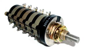
Grayhill Rotary Switch

Grayhill Rotary Switch


Above is an example of a Grayhill military rotary switch. You can see it has 5 decks. Each deck has 1 pole. Each pole has 9 positions.

This is an example of a 16 position rotary switch assembly 1-435304-1. This rotary switch assembly has a bar handle. It is a single pole but has 16 positions.

Five Easy Steps to Selecting the Right Switch

Although it is often one of the last components considered, selecting the correct switch is important when designing electronic equipment. Designers must be aware of the various options available in order to choose the most appropriate switch for any given application.
The procedure of selecting the correct switch can be summarized this way:

  • The requirements of the end user should be given consideration first
  • The engineering aspects like load, contact materials, terminal type, voltage, circuit type, mounting etc should be studied
  • Next the type of actuator should be decided
  • Standards like RoHS and similar government regulations must be complied with as well
  • Lastly, the switch chosen should be able to stand up to the rigors of the application. Environmental factors must be considered

When choosing a switch, you can ensure that the most appropriate switch is selected for the job if you take these factors into consideration.

Tact Switch – SKPFABA010

We’ve been selling a lot of this one particular switch – it’s called a long travel tact switch; manufactured by ALPS.

Here are some of the features of this switch:
— Dimensions: 8mm x 8mm
— Suitable for automotive applications due to its high operational force
— Malfunctions are prevented due to it having a longer travel than most conventional tact switches
— Easily mounted on a PC board with snap in leads
— Some of the output terminals can be used as jumper leads which makes the circuit arrangement simple

Here are some other uses:
— automotive electronic equipment
— communication devices
— measuring instruments

These switches are available right now – they have been priced lower than any other distributors.

Be sure to check them out next time you need a 12V tact switch!