Category Archives: Capacitors

What are Multilayer Chip Capacitors?

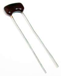
The electronics industry uses various types of capacitors in its circuits. These capacitors provide different capabilities and functionality depending on the type and construction. One of the most prevalent types of capacitors is the MLCC or multilayer ceramic capacitor.

Most MLCCs are applicable to circuits that require small-value capacitance. They are preferably useful as filters, in op-amp circuits, and bypass capacitors. This is because MLCC offers small parasitic inductance as compared to aluminum electrolytic capacitors. Therefore, MLCC offers better stability over temperature, subject to their temperature coefficient.

MLCC is available in three categories or classes. The Class I type of ceramic capacitors offer low losses and high stability in resonant circuits. Although they do not require aging corrections, their volumetric efficiency is low. Class II and Class III offer high volumetric efficiency, but their stability is not as good as that of Class I capacitors. Once outside the referee time of the manufacturer, Class II and Class III capacitors may require aging corrections. Manufacturers specify the referee time during which the capacitor will remain within the tolerance range.

Alternating layers of dielectric ceramic and metallic electrodes make up an MLCC. This structure makes them physically small but does not provide them with volumetric efficiency. Design engineers selecting MLCC for electronic applications look for two important parameters—voltage rating and temperature coefficient.

The voltage rating of the MLCC indicates the maximum safe voltage the circuit can apply across the capacitor terminals. For enhanced reliability, designers use a capacitor with a voltage rating higher than it will experience in the circuit. One advantage over electrolytic capacitors is that MLCCs are non-polarized. Therefore, it is possible to connect MLCC in any position without damage.

The temperature coefficient of an MLCC depends on its Class category. If the capacitor contains Class I ceramic material, it will have a very low-temperature coefficient, which means, a change in temperature will minimally affect the capacitance. Class I MLCC also tends to have low dielectric constants, which means the material offers very small capacitance per volume. For instance, C0G and NP0 type Class I MLCC feature a 0 temperature coefficient with a tolerance of ±30 ppm.

Class II MLCC, although less stable over temperature, contains ceramic material with a higher dielectric constant. That means Class II MLCC can have more capacitance in the same volume compared to that of Class I. Class II MLCC are available in X, Y, and Z temperature coefficients. For instance, X7R is a common Class II MLCC, and can operate within a temperature range of -55 °C and +125 °C with a tolerance of ±15%. X5R MLCC can operate within a temperature range of -55 °C and +85 °C with a tolerance of ±15%. Y5V MLCC can operate within a temperature range of -30 °C and +85 °C with a tolerance of +22/-82%. MLCCs with wider temperature ranges are also available with the higher stability of temperature characteristics. However, these capacitors tend to cost more.

Engineers use several capacitors with various values in parallel or series for providing the requisite impedance over a wide range of frequencies.

Motor Run & Motor Start Capacitors

Electric motors exploit the interaction between two magnetic fields for rotating a shaft. The stator windings generate one of the fields, and the rotor windings provide the other. In some DC motors, permanent magnets replace one of the windings, while the commutator, whether brushed or brush-less, changes the direction of the current in the other winding to continuously alter the interaction between the two magnetic fields to allow the motor to rotate.

In three-phase AC motors, the interaction between the three incoming phases creates the rotating magnetic field in the stator windings, and this pulls the rotor along, making it rotate. The so-called single-phase AC motor is, in reality, a two-phase AC motor that is operated with a single-phase supply, with capacitors generating the second phase. These motors require two capacitors, one to start the motor, and the other, to keep it running.

A capacitor is a device to store charge. In the DC circuit, a capacitor will charge up and stay that way until allowed a path to discharge. In the AC circuit, where voltage and current change polarity regularly, the capacitor charges up to the peak voltage in one cycle, then discharges and again charges up to the negative peak in the next cycle, with the rate of charging and discharging dependent on the capacitor value and the impedance in the circuit.

Another important factor is the voltage on the capacitor does not follow the input voltage while it is charging and discharging—it lags behind. Even though the supply voltage may be at its peak, the voltage on the capacitor reaches the peak only after the capacitor charges. Likewise, as the supply voltage moves towards the negative peak, the capacitor voltage follows more slowly as the capacitor has to first discharge. This lag helps to create the second phase for the motor.

A motor starting from rest requires a high starting torque, but once it has started moving, requires a smaller running torque to keep it in rotation. That means a larger capacitor is necessary for starting the motor—providing it with a larger starting current. In fact, motors use a centrifugal relay to cut out the start capacitor from the circuit after the motor has reached a certain speed. The run capacitor, though, has to remain connected to the motor at all times.

As the run capacitor is engaged in the circuit continuously, they are oil cooled and in metal, cases to allow heat dissipation. As they face peak to peak voltages all the time, their voltage rating tends to be on the higher side—typically, 1.5 times the line voltage, although the capacitance value may be low, ranging between 5 µF and 45 µF. On most 240 V systems, run capacitors are likely to be rated 370-440 VAC, and in 480 V systems, 600 VAC capacitors are more common. Run capacitors are rated for 100% duty cycle.

Start capacitors, being of larger capacity, are physically larger as well. As the start current does not need to be very precise, start capacitors are available as 8.3 µF, 15 µF, 43 µF, 60 µF, and above. Common voltage ratings for start capacitors are 110, 125, 165, 220, 250, or 330 VAC.

Seaweed For Making Superconductors and Supercapacitors

Seaweed, a kind of algae, and a part of cuisines in many parts of the world could be worked to supply power to electronics and other devices. Researchers have developed a material from seaweed to produce better superconductors, batteries, and fuel cells.

The research has been presented at a meeting of the American Chemical Society (ACS) on April 5, 2017.

Dongjiang Yang, PhD, a team member explains that carbon rich materials offer the most efficient energy storage solutions. Since the team wanted to use a green method for making superconductors, they chose seaweed, which is highly renewable as the base material. The scientists have intended to use seaweed extract as a template for fabricating a chain of porous materials that could be used to build the superconductors and energy storage solutions.

Although conventional carbon materials like graphite and graphene dominate the prevalent energy scenario, upcoming advances in storage devices could call for more sustainable materials. Yang, who is at Qingdao University in China, says that abundantly available seaweed could provide a more lasting solution in this regard. He has worked with colleagues in Griffith University in Australia and in Los Alamos National Laboratory in the US to devise a special kind of structure from the algae.

Egg-Box Structure

The scientists drew out porous carbon nanofibers from the seaweed extract by the process of chelating or binding. This process involved attaching cobalt ions to the alginate molecules of the seaweed. These molecules enveloped the cobalt metallic ions, which resulted in the formation of the nanofibers with a special structure resembling an egg-box. This structure contributes to the stability of the material so that the synthesis can be controlled.

Wide Range of Functions

Tests performed on the material showed that its reversible capacity is very high, around 625 mA hours per gram. This is much more than 372 mA hours per gram, which is the corresponding value for that of traditional graphite anodes used in lithium ion batteries.

Furthermore, the material performed as an efficient superconductor with a capacitance as high as 197 Farads per gram. This could be exploited in supercapacitors and zinc-air batteries. Tests also revealed that the performance of these egg-box nanofibers is as good as platinum-based catalysts used in fuel cells.

The scientists had first made public their findings on the egg-box structure in 2015. Since then they have been upgrading the technology involved. It is expected that there would be further improvements of the material.

For instance, the researchers explain that they have worked on the egg-box structure to reduce certain flaws in the seaweed structure that increased the motion of lithium ions. This helped to fabricate improved cathodes used in lithium ion batteries enhancing the performance.

In a more recent development, the researchers have forwarded a technique by which they have combined carrageenann, a variety derived from red algae with iron to prepare a carbon aerogel doped with sulfur. It has a very porous surface making for an extremely large surface area. The researchers say that this could be used very effectively in supercapacitors and in lithium sulfur batteries.

The researchers are now working towards commercial production of the seaweed-based devices.

What are Light-Emitting Capacitors good for?

HLEC, or Hyper-elastic Light-Emitting Capacitors are good for making electroluminescent skin for robotics, and you can do a lot with them. That is according to Dr. Rob Shepard of Cornell University and his team of graduate students, who have published a paper on the electroluminescent skin they have developed recently.

The team was inspired to develop the electroluminescent skin by observing several cephalopods such as the Octopus. According to the team, their material can change its color, just as an octopus can, including changing its size to fit into areas that structures that are more rigid cannot. For instance, the skin continues to emit light even when it has been stretched to about six times its original size.

Layers of transparent hydrogel electrodes separated with elastomer sheets as dielectric make up these HLEC or Hyper-elastic Light-Emitting Capacitors. Panels of these capacitors, integrated into robotic systems, and outfitted with sensors act as ideal health-based sensor applications for wearables. The team at Cornell has fabricated one robotic system from three panels and it is capable or crawling. With each panel consisting of six layers, the robot crawls along with worm-like movements, using two pneumatic actuators that alternately inflate and then deflate. You can see the stretchable skin and its crawling action in the video here.

Although the team is in raptures over how well the HLEC panels function, their next step is convert the material into practical devices with applications – find a reason to use it, as they say.

The team expects the development of uses for these new panels to lead to some innovative applications. Although at present, the speculated devices range primarily from health care to industries related to transportation, there is a significant interest in future robotic application as well. The latter is based on the interest in advancing the way robots interact with humans.

For instance, the robot Atlas, from Boston Dynamics, looks formidable enough to crush you were you to give it a hug accidentally. Humans prefer soft and puffy robots, and in the future, robots may even be able to change color based on the mood of the person in front. People generally grow an innate fear of robots after having watched T-800 in movies such as ‘The Terminator’. However, future robots such as Baymax should help make a difference in their thinking. According to Professor Shephard, HLEC panels can be part of the break-through.

It is important to get the human-robot interactions right. Simple things such as the ability to change their color can let robots make emotional connections with humans. This could be in response to the tone of the room or the mood of the humans in it.

This new electroluminescent skin has a huge potential for all kinds of new devices. However, it needs the assistance of other engineers as well to discover new applications and make use of this technology. Primarily, the material scientists who developed this skin are planning to use this for life-saving wearable health monitors. However, it could easily be used as a robot that fits into tight areas. Once the HLEC panels are commercially available, surely, there will be many people to think of additional innovative applications.

Mica Capacitors : Why should I use them?

mica capacitorMica, a phyllosilicate, is a group of hydrous potassium/aluminum silicate material. It is a rock-forming mineral exhibiting a two-dimensional sheet or layer structure. That means it is possible to split mica into thin sheets. The biggest advantage of mica is the excellent stability of its electrical, chemical and mechanical properties. This property makes mica a suitable material for use as a dielectric when making highly stable and reliable capacitors. Silver-mica capacitors are useful at high frequencies, because of their low resistive and inductive losses and high stability over time.

Delved in India, Central Africa and South America, the most commonly used are the muscovite and phlogopite mica. While the first has superior electrical properties, the latter has a higher temperature resistance. Mica capacitors are expensive as the raw material composition has high variation, requiring inspection and sorting. Silver mica capacitors have sandwiched mica sheets coated or plated with silver on both sides. The assembly is then encased in epoxy to protect it from the environment.

Tolerance and Precision

Among all types of capacitors, silver mica capacitors offer the lowest tolerances, as low as +/-1%. In comparison, ceramic capacitors have tolerances going up to +/-20% and electrolytic capacitors can have more.

The design of a silver mica capacitor does not allow any air gaps inside. Additionally, the entire assembly is sealed hermetically from the environment. That allows the mica capacitor to retain its value over long periods. As the assembly is protected from the outside effects of air and humidity, the capacitance of a mica capacitor remains stable over a wide range of temperature, voltage and frequencies. The average temperature coefficient of mica capacitors is around 50 ppm/°C.

Losses

Mica capacitors have a high Q-factor. This comes from the low resistive and inductive losses exhibited by these capacitors. That makes them a suitable choice for use at high frequencies, but it comes at a price – silver mica capacitors are expensive.

It is difficult for manufacturers to make silver mica capacitors of larger capacitance value. Typically, this ranges from a few pF up to a few nF. However, they can stand high voltages and mica capacitors are usually rated for voltages between 100 and 1000 volts. Special mica capacitors are rated up to 10KV and these are mostly for use with RF transmitters.

Applications

You can use silver mica capacitors wherever the application requires low capacitances, high stability and low losses – especially in power RF circuits – requiring very high stability.

You can also use silver mica capacitors in high frequency tuned circuits such as oscillators and filters. Pulsed applications such as snubbers also use mica capacitors as they can withstand high voltages. If cost is an important factor along with tolerance and low losses, you can replace mica capacitors with class I ceramic capacitors. Ceramic capacitors are available at a fraction of the price of mica capacitors.

Mica capacitors are available as surface mount versions as well. This offers several benefits over radial or axial assemblies. By eliminating the leads, SMT designs offer a smaller device size that can be mounted directly to the PCB – resulting in a more compact design and greater mechanical stability.

Powerful Energy Storage with Micro-supercapacitors

People have been trying to use supercapacitors to supplement batteries. Although capacitors do store energy, unlike batteries they charge up fast and discharge the energy stored quickly, such as in a camera flash. Common lithium-ion batteries take time to charge up and discharge according to requirement of the load. However, technology is catching up fast and new type of micro-supercapacitors is rivaling commercial supercapacitors in terms of storage capacity and power delivery similar to batteries.

At the Rice University, a team of researchers has developed a solid-state micro-supercapacitor. Although not a battery, this new device stores energy just as commercial supercapacitors can and it releases its stored energy just as a battery does. The specialty of the micro-supercapacitor developed by the researchers is it charges more than 50 times faster than batteries and discharges more slowly than traditional capacitors do.

The manufacturing process for these micro-supercapacitors allows them to be produced in a cost-effective and roll-to-roll method. The researchers used commercial lasers to burn electrode patterns in plastic sheets at room temperatures to form the basic structure of the supercapacitors. Manufacturing commercial supercapacitors involves several lithographic steps, making the process time-consuming and expensive. It also limits the widespread application of supercapacitors.

The new technique makes micro-supercapacitors in minutes, including burning the pattern, adding the electrolytes and packaging the devices. Since all this is done at room temperature, the fabrication process is simple, speedy, and cost-effective. According to the researchers, these micro-supercapacitors offer energy densities rivaling those offered by commercial thin-film batteries, while providing power densities nearly two times in magnitude. Additionally, they outlasted the batteries in terms of life and mechanical stability.

The energy density of micro-supercapacitors comes from laser-induced graphene or LIG. When the research group heated a commercial polyimide plastic sheet with a laser, they found it burnt everything. Only a top layer of carbon, in the form of graphene, was left over. However, this leftover layer was not a flat sheet of hexagonal rings of atoms, but a spongy array of graphene flakes that were attached to the polyimide. The LIG patterns etched into the plastic look like folded hands and the graphene has a huge surface area.

The researchers achieved capacitances of 934 mF per square centimeter, with energy density of 3.2 mW per cubic centimeter. This is at least twice that offered by commercial thin-film lithium batteries. In addition, the devices showed high resilience and mechanical stability even when repeatedly bent more than 10,000 times.

The researchers at Rice used electrodeposition to treat the LIG pattern of spongy graphene with manganese dioxide and ferric oxyhydroxide to turn the resulting composites into positive and negative electrodes. Forming the composites into solid-state micro-supercapacitors did not involve separators, binders, or current collectors. The entire process takes just minutes from burning the patterns, adding the electrolytes, and covering the capacitors.

The manufacturing process developed at the Rice University has great potential for bulk production of small and flexible micro-supercapacitors at room temperatures. The researchers are convinced that such plastic micro-supercapacitors will replace batteries entirely in the future.

What are Polymer and Hybrid Capacitors?

The growing complexity of active electronic components and their applications has resulted in the use of different types of passive components, especially capacitors. The advances in conductive polymers now offer a universe of capacitors for embedded systems applications and others.

Some advanced capacitors use conductive polymers for their electrolyte. Others such as hybrid capacitors use the conductive polymers in conjunction with a liquid electrolyte. Both these polymer-based capacitors offer improved characteristics over conventional ceramic and electrolytic capacitors, namely, life cycle, safety, longevity, reliability, stability, ESR or Equivalent Series Resistance and voltage rating. These special hybrid and polymer capacitors show distinct performance advantages in terms of ideal voltages, environmental conditions, and frequency characteristics.

Polymer Capacitors

Layered Polymer Aluminum Capacitors: These use conductive polymer as the electrolyte with an aluminum cathode. They operate within a voltage range of 2-25 VDC and manufacturers make them in capacities of 2.2-500 µF. Packaged in molded resin as low profile SMDs, they offer very low ESR.

Wound Polymer Aluminum Capacitors: Although they use conductive polymers and aluminum, they are constructed with a wound foil structure. They operate over a wider voltage range of 2.5-100 VDC and their capacities range from 3.3-2700 µF. With low ESR values, the capacitors are packaged as SMD, although layered capacitors are more compact in comparison.

Polymer Tantalum Capacitors: They use a tantalum cathode and conductive polymers as electrolyte. They are available in capacitance values of 2.7-680 µF and their operating voltage ranges from 1.8-35 VDC. Among the most compact capacitors on the market, polymer tantalum capacitors are available in SMD packages.

Hybrid Polymer Aluminum Capacitors: These use a combination of conductive and liquid polymers as electrolyte along with an aluminum electrode. The polymer offers low ESR as well as high conductivity. The liquid electrolyte offers higher capacitance ratings as it has a larger surface area, while being able to withstand high voltages. These capacitors come in a capacitance range of 10-330 µF with voltage range of 25-80 VDC. Although compared to other types, the ESR value for hybrid capacitors are on the higher side, the values are far lower than what conventional capacitors offer.

Advantages of Polymer Capacitors

Although different in material and construction, the four types of capacitors share common desirable electrical properties.

Superior Frequency Characteristics: As polymer capacitors have very low ESR, the impedance at their resonance point is also very low, resulting in reduced ripple in power circuits by nearly five times when compared to that produced by conventional tantalum capacitors.

Capacitance Stability: Ceramic capacitors tend to drift in response to DC bias and temperature. Polymer capacitors are devoid of such problems. This stability is of importance in automotive and industrial applications, where the operating temperatures vary broadly. Even under common operating conditions such as high temperatures and high frequencies, where ceramic capacitors show an effective capacitance loss of over 90%, polymer capacitors remain stable.

Enhanced Safety: Conventional capacitors can short circuit and fail, and these are causes for safety issues. Mechanical stresses or electrical overload can create discontinuities or defects in the oxide films that forms the dielectric leading to safety failures. The self-healing capability of the polymer capacitors eliminates such failure modes.

Why Do ICs Need Bypass Capacitors?

Any electronic design engineer will vouch for the necessity of supplementing integrated circuits on their PCB with bypass capacitors, although they may not understand the reason to do so very well. As a rule of thumb, engineers provide every IC with a 0.1µF ceramic capacitor next to its power pins in each circuit board they design. Along with proper PCB layout techniques, adding a bypass capacitor improves circuit performance and maximizes the efficacy of the ICs.

The trouble lies with transition currents. Circuits handling digital signals produce rapid transitions when their signals switch states. When digital circuits output a high state, the signal voltage is very close to the supply voltage. When they output a low state, the signal voltage reaches very near the ground voltage. When transiting from a low to high or a high to low, the voltage swing from supply to ground or from ground to supply, causes a transient current to be drawn from the supply.

Usually, power to an electronic circuit on a PCB is fed at a single point and traces on the PCB carry this power to each IC. Traces on the PCB have their own parasitic inductance, which, when coupled with the source impedance of the power supply, react to transient currents by creating voltage transients.

The trouble aggravates when ICs have to drive low-resistance or high-capacitance loads. The low-resistance demands high currents when the digital state changes from low to high. Again, when the digital state changes from high to low, there is a demand for the load current to reduce suddenly. However, according to Lenz’s Law, an induced current will flow such as to oppose the change that produced it.

The net effect of transient currents and the parasitic inductance of PCB traces and wires are to create high-magnitude voltage transients, ringing or severe oscillations in the power lines. This can lead to suboptimal circuit performance or even to system failure. Engineers at Texas Instruments have demonstrated an improperly bypassed line driver IC switching at 33MHz can induce ringing amplitude of the order of 2V peak-to-peak on a 5V power rail.

Placing a 0.1µF ceramic capacitor close to the IC power pins improves the situation, because capacitors store charge. Placing the bypass capacitor close to the IC allows low resistance and series inductance. The bypass capacitor is therefore in a better situation to supply or absorb the transients on the PCB traces, which have a comparatively larger resistance and series inductance.

Although engineers refer to such components as both bypass and decoupling capacitors, there is a subtle distinction between the two terms. Decoupling refers to the amount by which one part of the circuit influences another. Bypassing provides a low-impedance path allowing noise to pass by an IC on its way to ground. A capacitor, placed close to the IC supply pins, accomplishes both decoupling and bypassing. However, a decoupling capacitor has an additional task. It blocks the DC component of a signal and prevents it from traveling through to the next part of the circuit, while allowing the AC component little or no resistance at all.

Why Does My Motor Need A Capacitor?

Motor CapacitorIf you are using an AC pump to raise water from a sump to an overhead tank, chances are it uses a squirrel-cage type motor, which needs a capacitor to make it work. This is true for single-phase motors, where the capacitor creates an artificial second phase necessary to generate the rotating magnetic field and make the rotor start spinning. Once the rotor starts rotating, the interaction between the stator and rotor keeps the magnetic field spinning.

A single-phase motor has a primary winding and a secondary winding. If connected to the AC supply without the capacitor, both windings produce magnetic fields of the same phase resulting in zero torque. With a capacitor connected in series to the secondary winding, the magnetic field it produces lags behind the magnetic field generated by the primary winding. This difference in phases creates a starting torque and the motor starts to rotate.

Capacitors that allow a motor to start rotating are called start capacitors. Smaller motors usually have the start capacitor permanently connected in series to the secondary winding. Big motors require a larger capacitor to help them generate the starting torque, but they run more efficiently with a small capacitor in place, called run capacitor. Often both capacitors are housed in the same can, which then has three terminals in place of the customary two. Such motors have a centrifugal switch to disconnect the start capacitor when the motor has reached 70-75% of its full speed. Start capacitors are typically of high value of 100 or more microfarads, while run capacitors are smaller, of about 25-47 microfarads.

You will find motors with large start capacitors being used for several applications where it is necessary to generate considerable torque to begin moving the load. Such applications include mechanical conveyors, belted blowers and commercial garage door openers. These are mostly electrolytic capacitors, housed within a plastic or metal can. Inside the can are two metal foils rolled up with a flexible paper-like insulation separating the sheets. The paper, soaked with an electrolyte, forms the dielectric of the capacitor. The two metal foils are connected to two terminals. The assembly is sealed with epoxy and the two terminals are available for external electrical connection.

Large HVAC units sometimes need two run capacitors, because they have both a fan motor and a compressor motor. To save space, manufacturers combine the two physical capacitors into a single can. Such dual capacitors have three terminals and they are usually marked as Common, Fan and Compressor.

You will find a variety of combinations for dual capacitors, for example, 40 + 5uF, 370V or 100 + 25uF, 440V and others. Their shapes can be cylindrical with a round or oval cross-section. A capacitor’s ability to hold charge is measured in microfarads. As electrolytic capacitors age, their capacity reduces. That results in the motor failing to start or run at less than full speed.

Motors are not fastidious about the capacitance value of the capacitor used for starting. However, when replacing a faulty capacitor, you must never use a replacement that has a lower voltage rating. Always use a part with a voltage rating that is the same or higher than the rating of the capacitor you are replacing. Of course, it’s always preferred to replace a capacitor with another that has the exact electrical specifications for the best results – both in performance and safety.

The Ripple Rating of a Capacitor

Engineers do not prefer having ripples in their circuits and do their best to minimize its effects. For example, an AC source delivers power to an AC-DC converter that subsequently converts it to a steady DC output. It can be very inconvenient if the output were to have any source AC power appearing on top of the DC output in the form of small, frequency dependent variations. However, ripple may not be considered evil in all cases, as some digital signals could be useful to engineers as a necessary design function. Among these are signals that use changes in voltage levels to switch the state of a device and those generating clock timings.

As capacitors can store charge, they are useful for smoothening ripples in circuits. However, the designer must take care that the peak voltage does not exceed the voltage rating of the capacitor. It must also be noted that since there can be DC bias present in the circuit, the peak voltage will be the sum of the maximum ripple voltage and the DC bias. However, that is not enough for electrolytic capacitors.

Electrolytic capacitors are usually made with aluminum, tantalum and niobium oxide technologies and they have polarity. If the negative voltage of the ripple is allowed to drop below zero, this will cause a connected capacitor to operate under reverse bias conditions. Class II ceramic capacitors used in low frequency applications also suffer from this restriction.

A capacitor functions as a charge reservoir, charging with the rise of the incoming voltage and discharging into the load as it decreases – smoothening out the ripples in the process. Therefore, capacitors will see varying voltage. Additionally, depending on the power applied, the current through the capacitor will also vary, as will the intermittently pulsed and continuous power. This causes resultant changes in the electric field of the capacitor regardless of the incoming form and creates oscillating dipoles within the dielectric material, thereby self-heating the capacitor. Any parasitic inductance or ESL and resistance or ESR contributes to the energy dissipation.

That means a capacitor with low ESR, ESL and DF (dissipating factor), will heat up less than one with a dielectric characterized by high ESR and DF. However, as these parameters also depend on frequency, different dielectric materials offer optimum performance (lower heat generation) over different frequency ranges.

The dielectric in a capacitor is usually very thin constituting only a small amount of the overall mass of the capacitor. Other materials used in the construction also contribute to the heating when considering ripple – capacitor plates being one of the major contributors. Additionally, the conductive contacts also heat up to some degree when the capacitor carries an AC signal or current.

For example, at a certain frequency, if the capacitor with a 100mOhms ESR carries a 1A rms current, the power dissipated internally will be 100mW. If this power is supplied continuously, it will heat the capacitor internally until thermal balance is reached. Since this depends on ESR, the power dissipation is a function of frequency. However, the total thermal management will also depend on the capacitor’s environmental conditions, governing the heating up of the capacitor in an application.