Tag Archives: Connectors

New Clearance Categories and Products!

We are finally updating our clearance categories. We’ve added lots of new products to the subcategory pages including:

Click on the links above to see all the new products that have been added!

Standard Connectors for EV Charging

With EVs or electric vehicles becoming a trend for both individuals and commercial operations, more people are opting for them for commuting to work, school, and moving around the town. While there are tax benefits to using EVs, they also reduce our dependence on fossil fuels. Moreover, with the maturing of battery technologies, EV performance is comparable to those of vehicles with traditional internal combustion engines.

With the increasing number of EVs in use, their fundamental and foremost requirement is charging the battery. This aspect has led to a spurt in the growth of electric vehicle charging stations. Manufacturers of electric vehicles produce a range of vehicles that they base on their specific design specifications. However, charging devices need a uniform design so that any make or model of an electric vehicle can hook up for charging. At present, there are two categories of electric vehicle chargers—Level 1 and Level 2.

Level 1 chargers are available with the vehicle. They have adapters that the user can plug into a standard mains 120-Volt outlet. Manufacturers make these chargers common for use in home charging outlets.

Level 2 chargers are standalone types and separate from electric vehicles. They have adapters to plug into a 240-Volt outlet. These chargers are typically available in offices, parking garages, grocery stations, and other such locations. Homeowners may also purchase Level 2 chargers separately.

To allow any model or make of EV to connect to any Level 2 chargers, it is necessary for both the EV and the charger to use a standard connector. At present, the standard charger connector for Level 2 chargers is the SAR J1772. All the latest electric vehicles using plug-in charging use the standard SAE J1772 plug, while the charger connectors use the standard SAE J1772 adapters. These are also known as J plugs. J1772_201710 is the most current revision for the J plug specifications.

While SAE was originally an acronym for the Society of Automobile Engineers, presently they are known as SAE International. They often come up with recommended practices that the entire automobile industry accepts as standards. With the use of the standard SAE J1772 plugs, a customer purchasing an electric vehicle from any manufacturer can charge it using the same charging connector. Public electric charging stations also use the SAE J1772 chargers, and these are compatible with plugs in most vehicles from different manufacturers.

Each SAE J1772 charger has a standard coupler control system consisting of AC and DC residual current detectors, an off-board AC to DC high power stage, an auxiliary power stage, an isolation monitor unit, a two-way communication system over a single wire, contactors, relays, service and user interface, and an energy metering unit. Charging stations with J1772 connectors use a cable for charging the electric vehicle, and the rating of this cable is EVJE for 300 Volts or EVE for 600 Volts.

The EVJE/EVE cable consists of a thermoplastic elastomer jacket and insulation around a center conductor made of copper. The cable usually has two conductors of 18 AWG wire, one conductor of 10 AWG, and another conductor of 16 AWG.

Connector Use Lowers Wiring Costs

Contrary to popular belief, hardwiring does not always minimize wire installation expenses. Hardwiring is a popular concept for those who regularly design and build industrial machines. People perceive it as one of the most common ways of saving installation costs when bringing power and signal to the machine. However, when the full range of wiring costs are factored in, these cost savings really seem just as a mirage does.

Installation costs typically involve time and materials, including the cost of the wire, cables, accessories and labor. However, if you look closely, there are less obvious hidden installation costs as well. These have individual considerations for labor and time-to-market.

For example, consider machines that need to be disassembled for shipping and then reassembled before startup. That means parts in the machine will have to be hardwired twice – once while testing and then again after shipping. Additionally, errors while wiring in the field are quite common, mostly when local electricians unfamiliar with the machine are handling the wiring. If you are lucky, such errors may only cause a delay in commissioning the machine. However, there can be worst-case scenarios, and faulty wiring may even damage the machine leading to expensive repairs. Along with such cost of errors, hardwired systems can be complex and expensive to test, so the cost of testing goes up as well.

As a rule of thumb, you can expect the hidden costs to go up exponentially with the number of connection points the machine has. Fortunately, use of connectors can help avoid all these hidden costs. Of course, connector components do add an upfront investment, but this money will be recouped and then some as connectors enable lower-cost machines, the machines can ship faster, they can be commissioned more quickly and offer ongoing savings.

Using connectors, engineers can build modular machines faster and with lower expenses. This approach to machine design allows engineers to pre-build common subsystems and components, and test and stock them for installation. Reusable modules lead to many machines being designed with common control panels, junction boxes, motor assemblies and populated cable tracks.

Connectors are a real advantage for shipping new and large machines, especially if these machines have to undergo some level of disassembly also. Disassembly usually involves unplugging cables from the bulkhead connectors of the panel, while connections and routing internal to the panel remain undisturbed. The process holds true for sensors and data cables, motor assemblies and junction boxes also.

At the destination, the machine requires all disconnected wires to be reconnected once again. A local electrician helped with a set of wiring schematics can simply perform this. Even if the electrician knows very little about the machine and the way it works, there is little chance of them making costly mistakes and adding to startup delays. Most modern connector systems are designed to disallow simple wiring errors. Where large, complex machines are to be installed and commissioned, connectors can reduce the time to a matter of days in place of the several weeks that hardwiring would have taken.

High density card edge connectors

Sullins Connector Solutions, Inc., a San Marcos company from CA, has recently been including the FMBx series in their offerings. That has expanded their range of high-density 0.050-inch contact center card edge connectors. The company makes multiple versions of these connectors for various users. The new versions that are now available feature ultra-thin low profile and include high temperature devices that accommodate thicknesses of 0.093, 0.062 and 0.031 inches. At the same time, these versions support operating temperatures in the range of -65°C to +200°C. The low profile, ultra-thin interconnection are unique as their profile is only 0.488 inches.

The company is also offering 1.00mm versions that function within the same operating temperature range and these are ideally suited for ODMS and OEMs. The company, with its efficiency in manufacturing, is offering flexibility in design offering the customer maximum benefit. They make the connectors with an array of terminations, which includes surface mounting types, through-hole types, right angle or card extender types and types with staggered dip solder options. With the new product release, along with flexibility in design, the company is able to meet the diverse needs of the customer.

Sullins provide important features for their high-density card edge connectors along with several variations. For example, the 0.050-inch connectors, with operating temperatures of 200°C, are available with a low profile of 0.488 inches. In cases where there is a higher demand for thermal applications, profiles of 0.039 inch and 0.050 inch with operating temperatures of 125°C and 150°C are being offered. Based on the type of mating board and material selected, the reliability can be as high as 500 to 5,000 cycles. Options are available for card guides and molded key slots. Similarly, users have a choice in selecting the type of material, mounting styles and type of termination. In the market, the 0.050-inch connector is the only one rated at 3A.

Applications for these connectors are extremely diverse and widespread. The major areas among them are Radio Communications and Aircraft electronic Controls. They are also used in peripherals and computing equipment. You can see these connectors in Household Appliances, Consumer Electronics, Telecommunications, Burn in Ovens, Test Equipment, Casino Gaming Devices, Process Control Equipment, Industry Machinery, Medical Devices, and so on in a multitude of devices. The high-density card edge connectors cater to all these applications because of their flexibility in design combined with the company’s manufacturing efficiencies.

Sullins Connector Solutions started their operations in 1971 modestly. However, they are now positioned as a leader developing extremely reliable cutting-edge connectors. The Sullins now cater globally to very diverse applications. The company offers free samples on fast mode with only five days lead-time for shipping the customer’s confirmed order. Customers always have the backing of their technical support with connector experts to help on any specific project. The company is now offering 100% UL, CUL, and RoHS certified edge cards. The market is definitely going to benefit from the Sullins’ high-density edge card connectors with multiple options.

Connector Terms and Glossary

Are you a connector newbie? Below is a collection of terms relating to connectors with their corresponding definitions.

Attenuation – Decrease in power due to resistance or mismatch in transmission line.
Back Mounted – When applied to a coaxial connector it is that connector mounted from the rear of a panel with the fixing nut on the outside.
Bandwidth – Distance between two frequencies over which a RF or microwave device is intended to work.
Between Series Adaptor – An adaptor used to connect two different generic types of connector.
BNC – Bayonet Nut Connector.
Braid – A weave of metal strands used as an electrical shield for an insulated conductor or group of conductors.
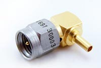
Connector

Connector


Bulkhead Mount – The type of connector fitted to a chassis using a single cut-out hole.
Cable Retention – The mechanism that joins the connector to the cable.
Cable Retention Force – The axial force which a connector / cable join can withstand.
Captive – A component such as a contact which is held firmly in position.
Characteristic Impedance – That impedance at which the transmission line is intended to work. A change from the characteristic impedance along its length will cause mismatch and loss of power.
Clamp – The holding of a cable by use of a screw thread action.
Closed Entry Contact – A female contact which is designed to prevent insertion of a contact larger than that specified.
Coaxial Cable – A transmission line where the one conductor is concentric inside another, often abbreviated to “coax”.
Coaxial Termination – A resistive element used to end a coaxial line in its characteristic impedance.
Coaxial Terminator – A device for terminating coaxial cable to a PCB or bulkhead mount (a mechanical device and should not be confused with coaxial termination)
Conhex – Tradename covering SMB and SMC, both in 50 Ohm and 75 Ohm impedance (discontinued)
Connector Durability – The number of times a connector can be physically mated and still maintain its specified performance.
Contact Resistance – The measurement of the DC electrical resistance between a pair of mated contacts. Usually specified as being measured after a given number of mating cycles.
Corona – A discharge of electricity caused by the ionisation of the air around a conductor just prior to total breakdown or flashover.
Crimp – The action of distorting a metal tube to give intimate contact with a conductor; a good crimp should be gas tight and not be impacted by environmental change.
Crimp Dies – The tool inserts which determine the shape of the distortion to create a consistently good crimp.
Crimp Tool – The tool which holds crimp dies to apply the necessary force.
Cross Talk – The amount of signal which may be transferred from one signal carrying line to an adjacent line.
Cut Off Frequency – The frequency at which the loss exceeds a predetermined level.
Decibel (dB) – A unit of measurement of RF power loss.
Dielectric – The insulating medium which holds the center conductor concentric within the connector or cable.
Dielectric Constant – The electrical value of dielectric which determines the impedance in cables or connectors with constant diameters.
Dielectric Withstanding Voltage – The maximum voltage that a dielectric material can withstand without failure.
Direct Solder – A common method of terminating connectors to semi-rigid cable by soldering the cable jacket to the connector.
Discontinuity – A dramatic change in characteristic impedance which gives rise to a reflected wave.
Dissipation – The unused or lost energy in a system e.g. heat.
Distortion – An unwanted change in a signal wave form.
Dummy Load – A device connected to the end of a transmission line to absorb transmitted power and prevent reflected energy.
Dust Cap – A mechanical device attached to the mating face of an unmated connector to prevent ingress of contaminants and provide protection against mechanical damage.
Electromagnetic Compatibility (EMC) – The ability of a device to operate within its intended environment without being effected by or generating electromagnetic interference (EMI).
Engagement and Separation Forces – The forces required to mate and unmate a pair of connectors. The forces are usually specified as a max & min for each action.
Environmentally Sealed – A connector that is provided with seals or other devices to prevent ingress of dust, moisture or other contaminants while mated which might impair performance.
Flexible Cable – A coaxial cable where the outer conductor is flexible (usually braided).
Gigahertz (GHz) – A measure of frequency representing 1 billion Hertz (cycles per second).
Impedance – See ‘Characteristic Impedance’
In-Series Adaptor – An adaptor which enables the connection of two connectors of the same generic type.
Insertion Loss – The loss of power due to a particular component in a transmission line (e.g. cable).
Insulation Resistance – The electrical resistance between two conductors separated by an insulating medium.
Intermodulation – The mixing of two or more frequencies which are not intended to mix.
Interface – The two surfaces of a connector which come into intimate contact when the two halves are mated.
Inter-series Adaptor – See ‘Between Series Adaptor’
Isolation – The measure of interaction between two or more transmission lines.
Jack – One half of a mating pair of connectors. The jack interface normally goes inside the plug interface.
Mean Power – The mean value of the rate at which energy is transmitted from one place to another.
Micro Strip – A transmission line consisting of a flat conductor on a dielectric above a single ground plane. (the ground plane is frequently a metalized face of the dielectric).
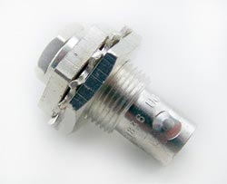
UG909B/U Female Bulkhead Clamp Kings Connector

UG909B/U Female Bulkhead Clamp Kings Connector

Microwave – Very short electromagnetic waves. Frequency range above 1 GHz.
MIL-C-39012 – The generic specification covering USA Military coaxial connectors.
MIL-C-17 – The generic MIL spec covering coaxial cables.
Mismatch – The condition in which the impedance of the source and load are not the = same. This reduces power transfer and causes reflections.
Mounting Plan – The design of the PCB or panel cut-out used to mount the connector. N Connector – This was the first true microwave connector capable of working to 18GHz, initially designed for test applications.
Nanohex – Trade name covering SSMB & SSMC (discontinued)
Noise – An external electromagnetic signal which interferes with the desired signal.
Non-captive – A component such as a contact which does not have a retention feature.
Passivation – This is a surface treatment applied primarily to stainless steel. The process removes contaminating iron particles and produces a passive surface.
Peak Power – Is the maximum power which may be handled by a connector or cable.
Plug – One half of a mating pair of connectors. The plug interface normally goes outside the jack interface.
POSNS – Abbreviation for “positions”.
PTFE – Abbreviation of polytetrafluorethylene. This is the most commonly used dielectric (insulator) used in professional coaxial connectors.
QPL – Qualified Parts List. Parts approved to MIL-C-390 12 specification.
Receptacle – A term used to describe a connector assembly usually bulkhead or PCB mounted.
Return Loss – A reason for loosing RF energy due to signals being reflected due to a mismatch in a transmission line.
RF Leakage – The RF power lost from a transmission line or device. Measured in dB.
RG – The traditional prefix for MIL spec coaxial cables.
Screw-on – The mating action of connectors which are joined using a screw thread (e.g. SMC)
Sealflex2â„¢ – Cannon trade name for a flexible microwave cable assembly which has a performance similar to semi-rigid cable.
Semi-rigid Cable – A coaxial cable where the outer conductor is a solid metal tube.
Skin Effect – The tendency of alternating currents to flow near to the surface of a conductor; this increases resistance and becomes more marked the higher the frequency.
SMD – Sometimes used as an abbreviation for slide-on variants of SMB. This is a misnomer, the more common use is for Surface Mount Device.
Snap-on – A term used to describe the mating action of SMB and SSMB connectors.
Solderless SMA – An SMA connector that can be connected to semi-rigid cable by compressing the inner body rather than by soldering (sometimes referred to as semi-rigid ‘crimp’ connectors).
Stripline – A method of building a microwave circuit. The circuitry is sandwiched between 2 ground planes. Sometimes referred to as Tri-plate.
Teflonâ„¢ – DuPont tradename for PTFE.
Tensile Strength – The greatest force a device can withstand without tearing or pulling apart. This is frequently the method of determining the effectiveness of a crimp.
TNC – Thread Nut Connector same size as BNC; the only obvious difference is the coupling nut.
Tri-plate – See Stripline.
UG Symbol – Used to indicate a connector made to US government spec.
Voltage Standing Wave Ratio (VSWR) – A way of expressing the resultant loss of power as a result of signal reflections due to discontinuity.