Tag Archives: Electronics Tutorials

Where Do You Use a Touchless Rotary Sensor?

Most touchless rotary sensors use a magnetic position marker for sensing position. The position marker is attached to the rotating part of the application. It also uses a sensor to measure the angle of the marker. The touch-less rotary sensor uses a magnetism-based technique and does not require physical contact between the marker and sensor. Although other noncontact magnetism-based sensors overcome the limitations of potentiometric sensors that use resistance-based track-and-wiper techniques, they still need a shaft to be attached to the housing of the sensor.

Touchless rotary sensors are the most suitable technology when you have:
• An application that requires measurements through a nonmagnetic plate or wall;
• An application working in extreme environments that necessitate the sensor shaft to be sealed;
• An application where the drive shaft vibrates or has a lot of play;
• An application that necessitates very low friction-torque requirements;
• An application where misalignment can be problematic.

Touchless sensors offer many advantages over conventional sensors. They have lower operating costs, are rugged, reliable, programmable and simple. Although the initial cost does seem higher than the alternatives, it is not always so. The alternatives often require expensive subcomponents such as ball bearings and or expensive precision shaft couplings.

Since the working core of a touch-less rotary sensor is always sealed from the environment, the sensor parts experience no mechanical wear. Although the magnet is exposed, it can be potted with ingress resistant compounds, especially when it is exposed to fluids. The sensor life is usually measured in MTTF or Mean Time To Failure.

There are two types of touch-less rotary sensors, customer programmable and preprogrammed, making it simple for the user. Where safety and is paramount, preprogrammed and pre-calibrated sensors can be used and their functionality cannot be altered. These are also less expensive as the sensors do not require any look-up table for calibration with microprocessors. Where precision and expanded functions are required for quick calibration of star and end angles, customer programmable touch-less sensors may be used.

To operate properly, both the sensor and the position marker attached to the rotating component of the machine must be appropriately sized and positioned. The magnet position markers come in several body styles. You can either screw them into the rotating component or clamp them onto the rotating shaft. The working distance between the sensor and the magnet is important and dictates the best magnet size. For example, if have a shaft with an axial offset in the X-Y direction, you will need a bigger magnet to compensate for the non-linearity and the drop in the axial tolerance band.

You can mount the sensor unit of the touchless rotary sensor system in the traditional servo-type mounts or in the two to four screw mount. The body of the sensor usually has mounting holes and slots and comes with screws for the mounting. This allows the sensor to be rotated and placed in an optimal mounting position before being secured.

Touch-less sensors typically measure rotary movements from 0-360 degrees with repeatability from 0.1-0.12 degrees. The resolution is typically from 10-14 bits. Most of the sensor units are rated to IP69.

How to measure temperature with a Raspberry Pi

Looking for another project to make with a Raspberry Pi? You can use your Raspberry Pi to measure temperature. Not only at a single point, but also at maximum of 20 points simultaneously. Of course, you will need 20 individual sensors for doing that. Raspberry Pi will poll all the 20 sensors one after the other, and read the temperature from each of the sensors.

If you are wondering how complicated it would be to wire up 20 sensors to the Raspberry Pi, you can relax, since you need only three wires in all. One of the wires will carry power to the sensors, one wire will be the ground or return path and the third wire is a unique 1-wire interface to control the sensor and to read the temperature measured by it.

This wonder sensor is a High-Precision 1-Wire Digital Thermometer, DS18S20, with a measurement range of -55°C to +125°C (-67°F to +257°F), a thermometer resolution of 9-bits and an accuracy of ±0.5°C from -10°C to +85°C. Maxim Integrated makes this thermometer and the smallest size is a little larger than a matchstick head (TO-92).

Not only can this tiny fellow read the temperature, it stores them in its non-volatile memory and can present them either as °C or as °F. You can set temperature limits in its memory and DS18S20 will tell you when the temperature it is monitoring goes beyond the programmed limits. You can use this thermometer with the Raspberry Pi to control thermostats, industrial systems, consumer products or any thermally sensitive system.

At this point, you may be wondering if there is only one single wire for all the 20 sensors, how is the Raspberry Pi able to differentiate the twenty temperature readings. Maxim has programmed each of the sensors with a unique serial number, and when Raspberry Pi wants to read the temperature from a specific sensor, it simply asks for it by the serial number of that sensor. Only the sensor whose serial number the Raspberry Pi queries, sends the temperature data, all the others remain silent.

The Raspbian Linux distribution that you are using in your Raspberry PI already has all necessary kernel modules installed for accessing the 1-wire bus. The programming details are rather simple and you can refer to them here.

What else can you do with a DS18S20 and Raspberry Pi? You may be measuring temperature at a remote place, or there is no space for the extra power supply to the DS18S20. So, instead of supplying power separately, you could make DS18S20 “steal” power from the 1-Wire bus. For this, you must connect the VDD pin of the DS18S20 to ground. According to the datasheet, do not use the parasitic mode for measurements above 100°C, as the DS18S20 will not be able to sustain communications.

If you have programmed temperature limits for some of the DS18S20s, they will raise a flag if the temperature they are sensing goes beyond the set points. By polling for the flags, Raspberry Pi can know, which sensor is sensing temperatures beyond its set point.

How to solder – an illustrated guide

Guide to learning to solderWe love when we come across electronics info and guides that others are sharing freely – and especially those that encourage others to share their knowledge and work.

For example…here is a fully illustrated guide to learning how to solder which was done by the fine folks at http://mightyohm.com. They’ve created a super guide with all the basics covered as well as some interesting tips and tricks that can make your soldering experience a little better. This would be a great staple for some basic electronics classes.

To see the full soldering guide, click on the image above.

Thank you to the creators of this comic book: Mitch Altman, Andie Nordgren and Jeff Keyzer. Great work!

The ins and outs of Peltier Cells

What Are Peltier Cells and How Do They Work?

If you join two dissimilar metals by two separate junctions, and maintain the two junctions at different temperatures, a small voltage develops between the two metals. Conversely, if a voltage is applied to the two metals, allowing a current to pass through them in a certain direction, their junctions develop a temperature difference. The former is called the Seebeck effect and the latter is the Peltier effect.

Many such dissimilar metal junctions are grouped together to form a Peltier cell. Initially, copper and bismuth were the two dissimilar metals used to form the junctions. However, more efficient semi-conductor materials are used in the modern Peltier cell. These are sandwiched between two ceramic plates and the junctions are encased in silicon.

Just as you could pass electric current through a Peltier cell to make one of its surfaces hot and the other cool, so could you place a Peltier cell in between two surfaces with a temperature difference to generate electricity. In fact, BMW places them around the exhaust of their cars to reclaim some electricity from the temperature difference between the hot gases emanating from the car and the atmosphere.

Another place where Peltier cells are put to use is the picnic basket. It connects to the car battery and has two compartments – one to keep food hot and the other to keep food and drinks cool. Unfortunately, Peltier cells are notoriously inefficient, since all they do is move heat from their cold side to the hot. Part of their efficiency is also dependent on how fast heat is removed from their hot side. Usually, Peltier cells are able to maintain a maximum temperature difference of 40°C between their hot and cold sides.

Active heat sinks use Peltier cells to keep CPUs cool inside heavy-duty computers. These CPUs pack a lot of electronics inside their tiny bodies and generate huge amounts of heat when working at high frequencies of a few Giga-hertz. Peltier cells help to remove the heat from the CPU and keep the temperature constant. One advantage in using Peltier cells for this work is the CPU can regulate the amount of heat removed. The CPU in a computer has temperature sensors inside and when it senses its temperature is going up, it pumps in more current into the Peltier to increase the heat removal.

What does the Peltier do with the heat it has acquired from the hot source? To maintain its functioning, the Peltier has to transfer this heat to the material surrounding its hot surface. Usually, this is an Aluminum or Copper heat sink, which then transfers the heat to the atmosphere.

Active heat sinks that are more exotic use heat-conducting fluids to transfer the heat away from the hot side of the Peltier cell. These are specially formulated fluids with high thermal conductivity running in pipes over the hot surface of the Peltier. As the Peltier gets hot, the fluid takes away the heat and changes to a liquid of a lower density. Convection currents are set up, causing the hot liquid to move away to be replaced by cooler liquid, aiding heat transfer. Heat from the hot liquid is removed in a heat exchanger in a different part of the computer.

What is a battery and how do they work?

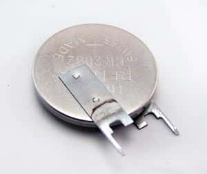
CR2032 battery

CR2032 battery

Batteries power most of our mobile gadgets. These are small chemical powerhouses, which generate electricity by the chemical reaction within the battery housing. Although there are different types of batteries available, all batteries contain cells that have two electrodes and a chemical or an electrolyte between them. Various combinations of series and parallel connections of the electrodes make up a certain voltage rating for the battery. For ease of understanding, we will treat the battery as made up of a single cell.

One of the electrodes is the cathode or the positive (+) terminal and the other is an anode or the negative (-) terminal. Because of the reaction between the two electrodes and the electrolyte inside, there is a buildup of electrons at the anode and a corresponding lack of electrons at the cathode. Although this is an unstable condition, and the electrons want to distribute themselves evenly between the electrodes, they cannot do so because of the presence of the electrolyte and its reaction with the electrodes. An isolated battery soon reaches a chemical equilibrium, and no further reaction occurs.

If the electrons find an alternate path to travel from the anode to the cathode, they will redistribute themselves and the number of electrons will gradually reduce, forcing the chemical reaction to start over again and create more electrons. This process continues until an inert layer covers one or both the electrodes. Usually, the alternate path is through a metal wire, which is a good conductor of electricity and links the two electrodes of the battery through a load or the mobile gadget requiring power.

Electrons flowing from the anode of the battery through the external wire to the load and back to the battery cathode constitute an electric current. Since it is usual to consider the direction of current flow as opposite to that of electron flow, we commonly say current flows from the cathode of the battery through the load and back to the battery’s anode.

Since the physical size of the battery restricts the quantity of chemical inside it, the current produced by the battery is also limited. The battery specification, as mAH or AH, is the product of the current and the number of hours the battery can produce this current continuously. In general, once the chemical within the battery has depleted itself or inert material has covered up the electrodes, the battery becomes useless. However, it is possible to revive or recharge certain types of batteries. These are the rechargeable batteries.

Once a rechargeable battery depletes itself, you can charge it up again by sending a current through it in a direction reverse to what it normally produces when connected to a load. This reverses the chemical reaction inside, and the electrolyte and the electrodes return to their initial condition. You can repeat this discharging and recharging process many times, until the electrolyte exhausts itself totally, and no further revival is possible.