Tag Archives: electronics projects

Get ready to talk to your gadgets

Google has many things always in the development stages so that they will remain at the forefront of action for internet users and smart phone users. Expectations are high that gadgets in the future will have voice-interface so that users can command different devices verbally. Talking to gadgets will be possible and Google is making sure that it is a part of such breathtaking developments. Smartphones will be the mode for talking to these gadgets and Google is gearing up to provide the necessary tools for the user for home activity from any location. The recent takeover of Nest Labs, which makes smoke detectors and thermostat controllers, by Google at an estimated deal of $3.2 billion, is thought to be precisely for that purpose.

Speaking to kitchen gadgets is likely to become a reality in the near future. The process is known as the “Internet of Things” and is likely to be in the thick of daily routine activities. When launched, it will totally change the nature of human activity at home and will enhance the popularity of the smartphone. According to the research company Gartner, Inc., the Internet is likely to be linked to more than 26 million objects suitable for verbal command and interface. Additionally, connectivity to PC, smartphones and tablets will substantially add to this figure. Tony Fadell is the founder of Nest Labs, and he is an Apple veteran who assisted in designing the iPhone and the iPod.

According to Forrester Research analyst, Frank Gillett, the reason Google bought Nest is “to learn about this world where even more information is going to be accessible by computers.” Nest has already been successful in offering thermostats to users for controlling the cooling and heating of devices at home. Nest, in the last few years, sold their products in the USA, Canada and the UK; it has been well received.

Google has not made any disclosures about the type of activity lined up for Nest for the immediate future. Angela McIntyre, the Gartner analyst, believes that, “They need to gather as much information as they can to understand the context in how we live our lives”, in order to take over all the activities which are routine and have no need for physical presence at home to perform it. It is likely that the mapping software from Google could be utilized to map out the home layout. This will be essential for delegating tasks to a robot if employed at home. It could also lead to navigation of the entire home from a remote place by a smartphone.

Although, at present, it is known that Google’s main source of revenue is from advertising and search requests, there is no doubt that the acquisition of Nest Labs is in the direction of involving with people’s personal activities in a more significant manner without in any way sacrificing their privacy. On the whole, Google could be of assistance with these new tools for people not at home to perform activities through the internet and smart phones even from remote places.

Gardening with the Raspberry Pi

Many of you may be garden enthusiasts and would welcome the idea of automating some of the maintenance requirements of your plants. For example, keeping tabs on the quantity of water that is required by the plants based on the moisture in the soil, the available sunlight and the environmental temperature might be easy for an experienced gardener. However, gardeners who have just started gardening find it a difficult equation to balance. Even an experienced gardener may have to depend on a novice if taking leave from his garden for a few days.

With a Raspberry Pi (RBPi), most of the above gardening issues can be fixed. The Raspberry Pi can take care of the garden’s watering requirements based on a few environmental measurements. This can bring relief to an experienced gardener forced to leave his beloved plants for a few days. The novice gardener can quit worrying if he is starving his plants or drowning them in water. This is how Devon approached the problem with his Raspberry Pi.

Avid gardening enthusiasts know that too much water to a plant can be as bad as too little. For the Raspberry Pi to determine how much water should be delivered to the plant, it is necessary to know how much moisture is present in the soil in the first place. That, combined with the temperature and the amount of available light can let Raspberry Pi control the pump that delivers the water to the garden.

Since Raspberry Pi is not capable of measuring analog signals that most sensors put out, an Analog to Digital Converter attachment is necessary. For this, using the MCP3008 ADC is a good choice since it allows eight sensors to be used at a time. For sensing the amount of sunlight available, a Light Dependent Resistor or LDR is useful. To measure the ambient temperature with some amount of precision, a temperature sensor such as the TMP35 or TMP37 will do. For sensing humidity in the soil, a homemade humidity sensor using a few long metal nails will be fine.

All the sensors will need a DC voltage supply and a return ground connection, with the signal from each sensor going to one of the channels of the ADC. The 3.3VDC from the Raspberry Pi board is good enough for the sensors. While only one temperature sensor and one LDR is enough, you may need more than one humidity sensor, depending on how big your garden is.

The humidity sensors check the resistance of the soil between a pair of probes inserted into the ground. As the soil dries up, the resistance increases between the two probes of the humidity sensor. If several such probes are placed at different places in the garden, the Raspberry Pi has a fairly good idea of the state of dryness of the soil in the garden.

The final and most important part of the entire system is the pump that delivers water to the garden. Using a tank and a submersible pump eliminates a whole bunch of issues that many gardeners face. You can experiment with drip-irrigation also if you like the idea. Devon has kindly shared the software and the code used, and you can download them here.

Sensing humidity using advanced technology

An approaching thunderstorm creates a very stuffy environment with oppressively heavy moisture in the air. The presence of water in the air is termed as humidity and this largely affects human comfort. The amount of water vapor influences many physical, chemical and biological processes. In industries, measuring and controlling humidity is critical since it can affect not only the health and safety of personnel, it can affect the business cost of the product as well.

Sleep apnea leads to repeated cessation of breathing during sleep. People, who suffer from sleep apnea, have to wear a mask to prevent nasal collapse. The mask is connected to a Positive Airway Pressure machine that sends pressurized air through the nasal passage of the patient, to prevent it from collapsing. It is important to monitor the humidity of the air the patient receives, keeping it at the appropriate level of comfort to allow the patient to sleep comfortably.

Traditionally, humidity or relative humidity was measured with the wet and dry bulb hygrometers. This method is neither accurate nor convenient in the industrial environment. With advancement in technology, solid-state devices are now available, which measure humidity with very high accuracy, repeatability and interchangeability. Solid-state humidity sensors are generally of two types, capacitive and resistive.

In resistive type humidity sensors, the resistance of the element changes responding to variations in humidity in the environment. The construction is in the form of two intermeshed printed combs, made of a thick film conductor of a precious metal such as gold or ruthenium oxide. The two combs form two electrodes, the space between them being filled with a polymeric film. This film has movable ions whose movement is governed by humidity. The film thus acts like a sensing film whose resistance changes with change in humidity.

The capacitive type of humidity sensor has an Alumina substrate on which the lower electrode is formed using either gold or platinum. A dielectric polymer layer such as thermoset polymer is then deposited on the lower electrode. This layer is sensitive to humidity. On top of this polymer layer, a top electrode is placed, and this is also made of gold or platinum. The top layer is porous and allows water vapor to pass through into the sensitive PVA layer. Moisture enters or leaves the sensing layer until the vapor content is in equilibrium with the environment. This sensor is therefore a type of capacitor whose capacitance changes with the change in humidity.

The arrangement of a hygroscopic dielectric material sandwiched between two pairs of electrodes, forms a capacitor whose value is governed by the dielectric constant of the hygroscopic material and the sensor geometry. At normal room temperatures, the value of the dielectric constant of water vapor is about 80, which is much larger than the constant of the sensor dielectric material. Therefore, as the sensor absorbs water vapor from the environment, it results in an increase in the capacitance of the sensor.

Both the resistive type and capacitive type of humidity sensors are available in the form of small surface mount SMD packages, and pre-calibrated to simplify, speedup manufacturing and reduce the cost for Original Equipment Manufacturers.

Where Do You Use a Touchless Rotary Sensor?

Most touchless rotary sensors use a magnetic position marker for sensing position. The position marker is attached to the rotating part of the application. It also uses a sensor to measure the angle of the marker. The touch-less rotary sensor uses a magnetism-based technique and does not require physical contact between the marker and sensor. Although other noncontact magnetism-based sensors overcome the limitations of potentiometric sensors that use resistance-based track-and-wiper techniques, they still need a shaft to be attached to the housing of the sensor.

Touchless rotary sensors are the most suitable technology when you have:
• An application that requires measurements through a nonmagnetic plate or wall;
• An application working in extreme environments that necessitate the sensor shaft to be sealed;
• An application where the drive shaft vibrates or has a lot of play;
• An application that necessitates very low friction-torque requirements;
• An application where misalignment can be problematic.

Touchless sensors offer many advantages over conventional sensors. They have lower operating costs, are rugged, reliable, programmable and simple. Although the initial cost does seem higher than the alternatives, it is not always so. The alternatives often require expensive subcomponents such as ball bearings and or expensive precision shaft couplings.

Since the working core of a touch-less rotary sensor is always sealed from the environment, the sensor parts experience no mechanical wear. Although the magnet is exposed, it can be potted with ingress resistant compounds, especially when it is exposed to fluids. The sensor life is usually measured in MTTF or Mean Time To Failure.

There are two types of touch-less rotary sensors, customer programmable and preprogrammed, making it simple for the user. Where safety and is paramount, preprogrammed and pre-calibrated sensors can be used and their functionality cannot be altered. These are also less expensive as the sensors do not require any look-up table for calibration with microprocessors. Where precision and expanded functions are required for quick calibration of star and end angles, customer programmable touch-less sensors may be used.

To operate properly, both the sensor and the position marker attached to the rotating component of the machine must be appropriately sized and positioned. The magnet position markers come in several body styles. You can either screw them into the rotating component or clamp them onto the rotating shaft. The working distance between the sensor and the magnet is important and dictates the best magnet size. For example, if have a shaft with an axial offset in the X-Y direction, you will need a bigger magnet to compensate for the non-linearity and the drop in the axial tolerance band.

You can mount the sensor unit of the touchless rotary sensor system in the traditional servo-type mounts or in the two to four screw mount. The body of the sensor usually has mounting holes and slots and comes with screws for the mounting. This allows the sensor to be rotated and placed in an optimal mounting position before being secured.

Touch-less sensors typically measure rotary movements from 0-360 degrees with repeatability from 0.1-0.12 degrees. The resolution is typically from 10-14 bits. Most of the sensor units are rated to IP69.

How to measure temperature with a Raspberry Pi

Looking for another project to make with a Raspberry Pi? You can use your Raspberry Pi to measure temperature. Not only at a single point, but also at maximum of 20 points simultaneously. Of course, you will need 20 individual sensors for doing that. Raspberry Pi will poll all the 20 sensors one after the other, and read the temperature from each of the sensors.

If you are wondering how complicated it would be to wire up 20 sensors to the Raspberry Pi, you can relax, since you need only three wires in all. One of the wires will carry power to the sensors, one wire will be the ground or return path and the third wire is a unique 1-wire interface to control the sensor and to read the temperature measured by it.

This wonder sensor is a High-Precision 1-Wire Digital Thermometer, DS18S20, with a measurement range of -55°C to +125°C (-67°F to +257°F), a thermometer resolution of 9-bits and an accuracy of ±0.5°C from -10°C to +85°C. Maxim Integrated makes this thermometer and the smallest size is a little larger than a matchstick head (TO-92).

Not only can this tiny fellow read the temperature, it stores them in its non-volatile memory and can present them either as °C or as °F. You can set temperature limits in its memory and DS18S20 will tell you when the temperature it is monitoring goes beyond the programmed limits. You can use this thermometer with the Raspberry Pi to control thermostats, industrial systems, consumer products or any thermally sensitive system.

At this point, you may be wondering if there is only one single wire for all the 20 sensors, how is the Raspberry Pi able to differentiate the twenty temperature readings. Maxim has programmed each of the sensors with a unique serial number, and when Raspberry Pi wants to read the temperature from a specific sensor, it simply asks for it by the serial number of that sensor. Only the sensor whose serial number the Raspberry Pi queries, sends the temperature data, all the others remain silent.

The Raspbian Linux distribution that you are using in your Raspberry PI already has all necessary kernel modules installed for accessing the 1-wire bus. The programming details are rather simple and you can refer to them here.

What else can you do with a DS18S20 and Raspberry Pi? You may be measuring temperature at a remote place, or there is no space for the extra power supply to the DS18S20. So, instead of supplying power separately, you could make DS18S20 “steal” power from the 1-Wire bus. For this, you must connect the VDD pin of the DS18S20 to ground. According to the datasheet, do not use the parasitic mode for measurements above 100°C, as the DS18S20 will not be able to sustain communications.

If you have programmed temperature limits for some of the DS18S20s, they will raise a flag if the temperature they are sensing goes beyond the set points. By polling for the flags, Raspberry Pi can know, which sensor is sensing temperatures beyond its set point.

Anti-static electronic component storage bins!

ESD Protection Bins

ESD Protection Bins

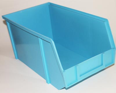
Great deal alert! We’re parting with some of our static dissipative stacking bins – taking them out of service in our warehouse. There’s still plenty of life available in these bins so grab them while you can at 60% off the price of new bins.

The bins are perfect for storing all your sensitive electronic components and supplies. Also ideal for a warehouse environment where you need some ESD protection.

Here are the larger size bins: Large Anti-Static Stacking Bin

And here are the medium size bins: Medium Anti-Static Stacking Bin

The price on these bins when new are $26 for the medium size and over $30 for the large size. Both sizes are stackable with an open hopper on the front side for easy access to the contents of the storage bin. Limited availability – only about 200 left.


New radial electrolytic capacitor assortment available!

Radial Electrolytic Capacitor Assortment

Radial Electrolytic Capacitor Assortment

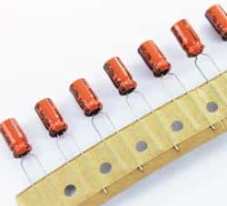
By popular request we’ve added an additional radial electrolytic capacitor assortment to our lineup of available products. Like our other capacitor kits, this assortment has a big range of capacitances and voltages supported. And like our other assortments, every value is individually bagged and labeled.

But here’s where this kit differs from our other previous kits – we are now able to provide a list of manufacturers and temperature ratings for this assortment so you can be sure that the capacitors in this assortment meet your needs. We’ve designed this assortment to be perfect for anyone’s workbench or ideal in a classroom setting.

Capacitor values range from 0.22uF 50V to 6800uF 10V. There are about 245 radial electrolytic capacitors included spanning 27 different values. Some of the included manufacturers are Taicon, Paccom, Sprague, NIC, Nippon, Marcon and Panasonic.

West Florida Components in the community making LED Throwies

West Florida Components was recently invited to participate in a science experiments fair held in conjunction with the USF Education Department.

Each business staffed a booth where elementary school aged kids along with their families could conduct science experiments. The community event was an opportunity for families to enjoy and see the benefits of science in a fun atmosphere. The West Florida Components station was one of about 18 stations at which participants could interact and have fun with science. The event met a significant need identified at the national, state and local levels which is to increase the scientific literacy of students as a way to improve the local, state and global competitive status of our communities and our country.

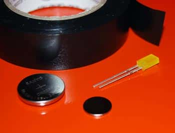
The staff from West Florida Components made LED Throwies with the fair attendees. Each family member was given an LED, a 3V battery, a magnet and some tape to put their LED Throwie together. Once the Throwies were assembled, they could toss their Throwie at a metal board to earn points. The families learned the science behind the Throwie and were given additional LEDS to take home to so they could rebuild their throwies and experiment further.

If you’d like the instructions to make the LED Throwies, you can visit our web site where we give full instructions with pictures.

Book for electronics beginners

If you are new to electronics and want a good book to learn about circuits and electronic components, then I recommend that you check out this book:

Getting Started in Electronics by Forrest M Mims III

I’ve had my copy so long that it is almost time to replace it but even though it is an old, worn out copy, the information is still as good today as it was 15 years ago when I got my book. Of course, there are some things that won’t be found in here, but for the beginner, you can’t go wrong with this book.

The chapters are logically laid out and easy to read and each chapter builds on the previous lessons. I would recommend this book for anyone who wants to learn about electronics – from child to adult.

Introduction to electronics

Introduction to electronics

Make a coin battery – great electronics project for kids!

What better way to illustrate how to build a basic electronic connection than to use coins to build a battery?

Here’s what you need:

Quarter

Quarter

quarters or dimes
aluminum foil
blotter paper (see below)
salt
cider vinegar
wire (short length of both black and red wire – ~16 gauge)
1 LED (any through hole LED)
scissors
pen or marker
voltmeter (optional)

~~~~~~~~~~~~~~~~~~~~~~~~~~~~~~~

Trace the coins on the aluminum foil and blotter paper. Cut out 10 of each so that you have 10 circles of aluminum foil and 10 circles of blotter paper.

(Blotter paper can be found in the art store or the art section of your local craft store. You can also find blotter paper in the cosmetics department. If you can’t locate blotter paper, then you can also try using thick paper towels.)

Mix a small amount (1/4 cup) of vinegar with some salt. Stir the salt until dissolved. If the salt can not dissolve, then you’ve added too much. Add some additional vinegar and stir. Soak the circles of blotter paper in the vinegar and salt mixture.

Stack the foil, blotter paper and coins as shown in the video. It is important that the foil not touch the other layers. Let the ‘battery’ stand for about 15 minutes to develop a charge.

Connect each lead of the LED to a short piece of wire; the black wire connects to the negative lead and the red wire is attached to the positive lead on the LED. Place the exposed end of negative wire on the bottom of the ‘battery’ touching the foil, and the end of the positive wire to the quarter on top of the stack.

Optional: Use the voltmeter to measure how many volts are generated by the battery. A battery with 6 or more cells should be able to light up a standard LED with no problem!