Category Archives: Electronics History

What Is Ultrasonic Ranging?

Ultrasonic technology has some unique advantages over other types. With ultrasonic methods, you can solve several application problems that become cost prohibitive or simply cannot be solved by other methods. Some of these are: long range detection, broad area detection, widest range of targeted materials and non-contact distance measuring.

In simplest terms, ultrasonic ranging is a method of echo-location. Most of us have used echo-location to know the distance to the cliff producing the echo, the distance of the thundercloud or the depth of a deep well. The principle is simple, note the time taken for the sound to travel and multiply it with the speed of sound. For example, you may hear the sound of thunder 3 seconds after you see the flash. The source of the sound is then 3 times 330 or 990 meters away, as sound travels roughly at 330 meters every second in air. Thunder is visible almost instantaneously, as light travels nearly 1,000,000 times faster than sound does.

The only difference in ultrasonic ranging is the use of sound frequencies that are beyond the range of normal human hearing. Young humans can hear sounds with frequencies ranging from 20 Hz to 20 KHz, with the upper limit dropping off to 15 KHz or even to 10 KHz with advancing age. Frequencies of 30 KHz to 40 KHz are common in ultrasonic ranging.

In ultrasonic ranging, a burst of high-frequency sound is generated, and a timer is started simultaneously. The timer stops as soon as the echo arrives. The burst of sound leaves the transmitter, hits the target object and returns to the receiver. Therefore, it took only half of the total time elapsed for the sound to reach the target object. This half-time multiplied by the speed of sound in the medium gives the distance of the target object from the source of the sound.

Although the sensors for producing the ultrasonic sound and for receiving it may take many complicated shapes depending on the actual application, for general purpose ultrasonic ranging, the sensor module looks like:

The associated electronics on board the sensor module consists of a microprocessor programmed to generate a burst of sound on trigger. The microprocessor also measures the time taken to receive the echo (time of flight) and thereby calculates the distance.

Ultrasonic ranging is mostly used in two ways for locating objects – proximity detection and precise range measurement. In proximity detection, any object passing within the preset range will be detected and the module will generate an output signal. The detection will be independent of object size, material or degree of reflectivity.

Ultrasonic ranging is also used for precise measurements of an object moving to and from the sensor. As explained earlier, the time of flight is measured for calculating the distance between the sensor and the object. By repeatedly sending sonic bursts and measuring the echo received, the distance of change is continuously calculated and displayed.

Depending on the frequency of sound generated by the ultrasonic transducer, the sensing range can vary from a few centimeters to about 10 meters.

Are OLEDS better than LEDS?

Chances are, you still own a TV that is bulky, has a picture tube and is kept on a table. Well, with advancing technology, TVs have become slimmer and lighter, can hang on the wall and do not have a bulky picture tube.

The new TVs have an LCD or a Liquid Crystal Display in place of the earlier picture tube. Now, unlike the picture tube, LCDs have no light of their own, and have to be lit with a backlight. Until recently, most LCD TVs were backlit with plasma discharge tubes or CCFL lamps.

The CCFL lamps are placed directly behind the LCD panel and this adds to the overall thickness of the TV. Another newer method of lighting up the LCD panel is with LEDs and these are placed all around the panel, just beneath the bezel of the screen. Some models, especially the larger sized TVs place the LEDs behind the panel.

According to the TV manufacturers, LED models provide a better contrast (difference between black and white parts of the picture). This is because LEDs can be turned off completely to render a complete black portion. With CCFLs, there was no turning off, and the blacks produced were not so deep.

With further advancement of technology, there is a new kid on the block, called OLED or Organic Light Emitting Diode. This is a thin layer of film made from an organic compound which emits light in response to an electric current. Unlike an LCD, an OLED screen needs no backlighting, making it the thinnest of all the screens for a TV; a screen, which can be rolled up.

Other advantage of OLEDs is its very high switching speed, which produces practically no blur when there is fast movement in the picture. Moreover, OLEDs can be switched off to produce black color, and there is no leakage of light from the neighboring OLEDs. This allows OLEDs produce the highest dynamic contrast among all the displays. Does that mean OLEDs are better than LEDs?

As the technology is relatively new, there are some primary difficulties that OLEDs face today. The first is OLEDs are still not as bright as LEDs are, and that makes them harder to see in sunlight or even in broad daylight. Additionally, with the present structure of the OLEDs, producing blue light is harder. This makes the images just passable.
Another issue with the OLEDs is their lifespan. At present, the OLED has the shortest lifespan among LED, LCD and other technologies commonly available on the market. The average lifespan of an OLED is only 14,000 hours, which means if you watch eight hours of TV every day, the OLED screen will last only five years.

Although OLEDs are good at displaying high contrast, they hog quite a bit of power when displaying all whites. Moreover, similar to the old cathode ray tubes or picture tubes, OLEDs are prone to burn-in, meaning if you let the picture remain static for long, a shadow of the picture remains on the screen.

The last disadvantage of OLEDs is their prohibitive cost.

Linear Variable Differential Transformers (LVDT)

Did you know that the innocent looking solenoid could be the basis of an extremely sensitive, accurate and repeatable measuring transducer? Of course, it does not remain as a simple solenoid anymore, two more coils are added to it, and its length may increase. That is about all the changes that are required to transform a solenoid into an LVDT or Linear Variable Differential Transformer.

This common form of an electromechanical transducer converts a linear or rectilinear motion of the object to which it is coupled mechanically, into an electrical signal that can be readily monitored on an oscilloscope. LVDTs not only measure movements that are only a few millionths of an inch, but can also measure positions that vary by +/-20 inches.

The LVDT has a primary winding that is sandwiched between two secondary windings that are identical. The windings are on a one-piece hollow form of a glass-reinforced polymer, which is thermally stable. The whole arrangement is secured within stainless-steel housing.

The moving element is a separate tubular armature core, made of a magnetically permeable metal. This core is moves freely within the hollow bore of the housing. As it is, an LVDT is more like a cross between an electrical transformer and a solenoid.

In operation, the primary winding of the LVDT is energized by an alternating current signal. Part of the flux generated is coupled to the secondary windings because of the core. If the core is exactly mid-way between the two secondary windings, the coupling is equal and an anti-phase connection between the two windings shows a null or no output on the oscilloscope. If the core moves to one side, the secondary winding on that side has a greater coupling, and its output increases, while the output of the other secondary coil falls because of reduced coupling. A corresponding output is visible on the oscilloscope.

The output of an LVDT is the differential voltage between the two secondary windings, and varies linearly with the axial positioning of the core within the hollow bore of the LVDT. In actual practice, the differential voltage is converted to a DC voltage or current, as these are easy to measure using conventional measuring instruments rather than an oscilloscope.

If the output of an LVDT is represented graphically, it is easy to see what makes the whole arrangement such a versatile and sensitive transducer. The null point is a highly defined position and very repeatable. Since the position of the core is defined mechanically, electrical power interruption does not cause the readings to change. The output is highly linear and does not require further conditioning.

Advantages of LVDT

• Since the operating friction is low, it is useful for many applications requiring light loading;
• Can detect very low displacements, is repeatable and is highly reliable;
• Long life due to minimal wear and tear – suitable for critical applications like nuclear, space, etc.;
• Safety from over-travel of the core – the core can come out of the hollow completely without damage;
• Sensitive only in the axial direction – not affected by misalignment or cross-direction movement;
• Core and coil assembly readily separable;
• Rugged, minimal impact of environmental variations, good shock and vibration immunity;
• Responds rapidly to changes in the position of the core.

What Are Proximity Sensors?

Those of you who use a mobile phone with a touch-screen may have wondered why items on the touch-screen do not trigger when you hold the phone to your ear while answering a call. Well, designers of mobile phones with touch-screen have built-in a feature that prevents a situation such as “My ear took that stupid picture, not me.” The savior in this situation is the tiny sensor placed close to the speaker of the phone, and this proximity sensor prevents touch-screen activity when anything comes very close to the speaker. That is what happens when your ear touches the screen as you are on a call, but does not generate any touch events.

So, what sort of proximity sensors do the phones use? Well, in most cases, it is an optical sensor or a light sensing device. The sensor senses the ambient light intensity and provides a “near” or “far” output. When nothing is covering the sensor, the ambient light falling on it makes it give out a “far” reading, and keeps the touch-screen active.

When you are on a call, your ear covers the sensor, obstructing the device to see ambient light. Its output changes to “near” and the phone ignores any activity from the touch-screen, until the sensor changes its state. Of course, the mobile phone considers more complications such as what happens when the ambient light falls very low, but we will discuss more on different types of proximity sensors instead.

Different types of proximity sensors detect nearby objects. Usually, the proximity sensor is used to activate an electrical circuit when an object either makes contact with it or comes within a certain distance of the sensor. The sensing mechanism differentiates the types of sensors and these can be Inductive, Capacitive, Acoustic, Piezoelectric and Infra-Red.

You may have seen doors that open automatically when you step up to them. When you are close to the door, the weight of your body changes the output of a piezoelectric sensor placed under the floor near the door triggering a mechanism to open the door.

Cars avoid bumping into walls while backing. The proximity sensor (a transmitter and sensor pair) used here works acoustically. A pair is fitted on the backside of the car. The transmitter generates a high frequency sound signal and the sensor measures the time difference of the signal bounced back from the wall. The time difference reduces as the car approaches the wall, telling the driver when to stop.

Computer screens inside ATM kiosks and the screen on your mobile are examples of capacitive proximity sensors. When you put a finger or a style on the screen, the device detects the change in the capacitance of the screen. The device measures the capacitance change in two directions, horizontal and vertical, or in x and y directions, to pinpoint the exact location of your finger and operate the function directly underneath.

When a security guard checks you out with a wand, or you walk through a metal detector door, the guard may ask you to remove your watch, coins from your pocket and in many cases, even your belt. The reason is the wand or the door has an inductive proximity sensor that will trigger in the presence of metals (mostly made of iron or steel).

Finally, the fire detector in your home or office is a classic example of a proximity sensor working on Infrared principles. Level of infrared activity beyond a threshold will trigger the alarm, and bring the fire brigade rushing.

How Does the Touch Screen on a Mobile Phone Work?

The mobile phone is an amazing piece of work. Earlier you had to press buttons, now you just touch the app on your screen and it comes to life. You can even pinch your pictures to zoom in on a detail or zoom out to see more of the scene. The movement of your finger in the screen causes the screen to scroll up, down, left or right.

The technology behind this wizardry is called the touch-screen. It is an extra transparent layer sitting on the actual liquid crystal display, the LCD screen of your mobile. This layer is sensitive to touch and can convert the touch into an electrical signal, which the computer inside the phone can understand.

Touch screens are mainly of three different types – Resistive, Capacitive and Infrared, depending on their method of detection of touch.

In a resistive touch-screen, there are multiple layers separated by thin spaces. When you apply pressure on the surface of the screen by a finger or a stylus, the outer layer is pushed into the inner layers and their resistance changes. A circuitry measuring the resistance tells the device where the user is touching the screen. Since the pressure of the finger or the stylus has to change the resistance of the screen by deforming it, the pressure required in resistive type touch-screens is much more than for capacitive type touch-screens.

Capacitive type touch-screens work on a principle different to that of the resistive touch-screens. Here the change measured is not in terms of resistance but of capacitance. A glass surface on the LCD senses the conductive properties of the skin on your fingertip when you touch it. Since the surface does not rely on pressure, the capacitive touch-screens are more responsive and they can respond to such gestures as swiping or pinching (multi-touch). Unlike the resistive type screens, the capacitive screen will only respond to touch by a finger and not to stylus or a gloved finger, and certainly not to fingers with long nails. The capacitive touch-screens are more expensive and can be found on high-end smartphones such as from Apple, HTC and Samsung.

As the screen grows larger, such as for TVs and other interactive displays such as in banking machines and for military applications, the resistive and capacitive type technologies for touch sensing quickly become less than adequate. It is more customary to use infrared touch screens here.

Instead of an overlay on the screen, infrared touch screens have a frame surrounding the display. The frame has light sources on one side and light detectors on the other. The light sources emit infrared rays across the screen in the form of an invisible optical grid. When any object touches the screen, the invisible beam is broken, and the corresponding light sensor shows a drop in the signal output.

Although the infrared touch-screens are the most accurate and responsive among the three types, they are expensive and have other disadvantages. The failure rate is high because diodes used for generating the infrared rays fail often.

The ins and outs of Peltier Cells

What Are Peltier Cells and How Do They Work?

If you join two dissimilar metals by two separate junctions, and maintain the two junctions at different temperatures, a small voltage develops between the two metals. Conversely, if a voltage is applied to the two metals, allowing a current to pass through them in a certain direction, their junctions develop a temperature difference. The former is called the Seebeck effect and the latter is the Peltier effect.

Many such dissimilar metal junctions are grouped together to form a Peltier cell. Initially, copper and bismuth were the two dissimilar metals used to form the junctions. However, more efficient semi-conductor materials are used in the modern Peltier cell. These are sandwiched between two ceramic plates and the junctions are encased in silicon.

Just as you could pass electric current through a Peltier cell to make one of its surfaces hot and the other cool, so could you place a Peltier cell in between two surfaces with a temperature difference to generate electricity. In fact, BMW places them around the exhaust of their cars to reclaim some electricity from the temperature difference between the hot gases emanating from the car and the atmosphere.

Another place where Peltier cells are put to use is the picnic basket. It connects to the car battery and has two compartments – one to keep food hot and the other to keep food and drinks cool. Unfortunately, Peltier cells are notoriously inefficient, since all they do is move heat from their cold side to the hot. Part of their efficiency is also dependent on how fast heat is removed from their hot side. Usually, Peltier cells are able to maintain a maximum temperature difference of 40°C between their hot and cold sides.

Active heat sinks use Peltier cells to keep CPUs cool inside heavy-duty computers. These CPUs pack a lot of electronics inside their tiny bodies and generate huge amounts of heat when working at high frequencies of a few Giga-hertz. Peltier cells help to remove the heat from the CPU and keep the temperature constant. One advantage in using Peltier cells for this work is the CPU can regulate the amount of heat removed. The CPU in a computer has temperature sensors inside and when it senses its temperature is going up, it pumps in more current into the Peltier to increase the heat removal.

What does the Peltier do with the heat it has acquired from the hot source? To maintain its functioning, the Peltier has to transfer this heat to the material surrounding its hot surface. Usually, this is an Aluminum or Copper heat sink, which then transfers the heat to the atmosphere.

Active heat sinks that are more exotic use heat-conducting fluids to transfer the heat away from the hot side of the Peltier cell. These are specially formulated fluids with high thermal conductivity running in pipes over the hot surface of the Peltier. As the Peltier gets hot, the fluid takes away the heat and changes to a liquid of a lower density. Convection currents are set up, causing the hot liquid to move away to be replaced by cooler liquid, aiding heat transfer. Heat from the hot liquid is removed in a heat exchanger in a different part of the computer.

Parental Control V-Chip – What is it and how does it work?

Parents are concerned over the type of programs their children watch on the television and would like to exercise their control. They do not want their children watching programs with excessive violence or sexual content. Since it is not possible to be always present when the children are watching TV, it is best to have a device automatically detecting the type of program coming through, and blocking it if it is objectionable.

All television sets made and sold in the US after 1999 have a special electronic chip built in and this is the V-chip. This allows parents to select the level of violent programs, which children can watch in the home. This also means that all TV programs contain a rating transmitted along with the program, which the V-chip can detect.

The FCC defines the ratings as –

TV-Y – Suitable for all children, with no violence and no sexual content
TV-Y7 – Suitable for children aged seven and over
TV-G – Suitable for general audiences, with no violence, no sex and inappropriate language
TV-PG – Parents to exercise their own discretion
TV-14 – Suitable for children above 14 only, with some violence and sex
TV-MA – Suitable for mature audiences only and may contain sexual situations and/or graphic violence

A parent can program the V-chip with a specific rating, and the chip will block all programs or shows above that rating. For example, if you have programmed a V-chip for a TV-G rating, it will allow all programs with a rating of TV-G, TV-Y7 and TV-Y, and will block all the rest.

All television programs transmit synchronizing signals, which allow a proper build-up of the picture on the screen. The electron beam painting the picture on the screen starts to sweep from the top left corner to the right edge of the screen, turns itself off, retraces itself to the left edge and sweeps again to the right edge, moving down a tiny bit in the process, until it has covered the entire height of the screen. The beam then returns from the bottom right hand corner of the screen to the top left hand corner and the whole process repeats. The vertical and horizontal retrace signals transmitted along with the TV program control all this.

As the signal returns from the bottom of the screen to the top, it follows a number of horizontal retrace lines. The twenty-first line of the horizontal retraces has data embedded in it as specified by the XDS standard. This includes captioning information, time of the day, ratings information and many others.

The V-chip is capable of reading this line 21 data, extracts the rating’s information and compares it with the parent’s allowed rating. Accordingly, the chip lets the signal pass through or blocks it.

The V-chip in the television works in conjunction with the cable box and/or the VCR. You can either utilize the V-chip or turn it off.

What is a battery and how do they work?

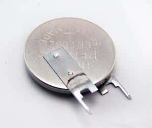
CR2032 battery

CR2032 battery

Batteries power most of our mobile gadgets. These are small chemical powerhouses, which generate electricity by the chemical reaction within the battery housing. Although there are different types of batteries available, all batteries contain cells that have two electrodes and a chemical or an electrolyte between them. Various combinations of series and parallel connections of the electrodes make up a certain voltage rating for the battery. For ease of understanding, we will treat the battery as made up of a single cell.

One of the electrodes is the cathode or the positive (+) terminal and the other is an anode or the negative (-) terminal. Because of the reaction between the two electrodes and the electrolyte inside, there is a buildup of electrons at the anode and a corresponding lack of electrons at the cathode. Although this is an unstable condition, and the electrons want to distribute themselves evenly between the electrodes, they cannot do so because of the presence of the electrolyte and its reaction with the electrodes. An isolated battery soon reaches a chemical equilibrium, and no further reaction occurs.

If the electrons find an alternate path to travel from the anode to the cathode, they will redistribute themselves and the number of electrons will gradually reduce, forcing the chemical reaction to start over again and create more electrons. This process continues until an inert layer covers one or both the electrodes. Usually, the alternate path is through a metal wire, which is a good conductor of electricity and links the two electrodes of the battery through a load or the mobile gadget requiring power.

Electrons flowing from the anode of the battery through the external wire to the load and back to the battery cathode constitute an electric current. Since it is usual to consider the direction of current flow as opposite to that of electron flow, we commonly say current flows from the cathode of the battery through the load and back to the battery’s anode.

Since the physical size of the battery restricts the quantity of chemical inside it, the current produced by the battery is also limited. The battery specification, as mAH or AH, is the product of the current and the number of hours the battery can produce this current continuously. In general, once the chemical within the battery has depleted itself or inert material has covered up the electrodes, the battery becomes useless. However, it is possible to revive or recharge certain types of batteries. These are the rechargeable batteries.

Once a rechargeable battery depletes itself, you can charge it up again by sending a current through it in a direction reverse to what it normally produces when connected to a load. This reverses the chemical reaction inside, and the electrolyte and the electrodes return to their initial condition. You can repeat this discharging and recharging process many times, until the electrolyte exhausts itself totally, and no further revival is possible.

What is a MOS-FET?

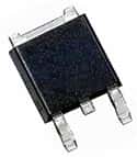
Mos-FETMOS-FET, which is an abbreviation of Metal-Oxide-Semiconductor Field Effect Transistor, is a very important kind of transistor. Many IC’s are constructed of arrays of MOS-FETS on a tiny sliver of silicon.

They are very small, easy to manufacture and many MOS-FETS consume a small amount of power making them an excellent choice for many applications.

It is the most common type of transistor available for either digital or analog circuits, replacing the bipolar transistor which was much more common in the past.

The word ‘metal’ in the name is actually now a misnomer because what was originally the gate material (often Aluminum) is now more often a layer of polysilicon (aka polycrystalline silicon).

Schottky Diodes – What makes them so special?

Some of the most common questions we get are about Schottky diodes.

Schottky Diode

The simple definition of a Schottky diode is a diode with a very fast switching action as well as a lower forward voltage drop.

As the current flows through a diode, it experiences a slight voltage drop across the diode terminals. Normally, a diode has approximately 0.7-1.7V drops. A Schottky diode, however, will see a drop in voltage between 0.15-0.45V. The benefit of this lower drop? A much higher system efficiency.

The construction of a Schottky diode also effects the voltage drop and switching time. A Schottky diode has a metal semiconductor junction as the Schottky barrier rather than the traditional semiconductor to semiconductor junction seen in conventional diodes. It is this barrier that affects the voltage drop and the speed of the switching times.

Sometimes Schottky diodes are misspelled by adding an ‘e’ to the end: Schottkey. The correct spelling is Schottky which is the surname of the man that is credited with putting these electronic components in the history books.