Tag Archives: electronics projects

How to Make Your Own LEDS? Whooooooooa

I found this how-to today on the great Popular Science web site.

Now that I’ve read through the article – I am amazed that I’ve never seen these instructions written up before.

Theodore Gray, who authors their popular “Gray Matter” column, gives the full scoop on the basic materials used to construct LEDS and provides the basic instructions needed to see just how LEDS work.

OK, it is not so easy to find some synthetic silicon carbide (carborundum) laying around, but surely everyone could get their hands on some sandpaper, needles, a 9V battery and a snap. Follow his instructions, and VOILA…you’ve recreated the basic principles behind the creation of LEDS.

Custom Console Stereo

For those of you wanting to hear just how good a custom built vacuum tube amp or console stereo will sound, here’s a video from Steve at Custom Tube Art which shows the workmanship of his projects and the quality of the sound.

Steve had this to say about his latest project:

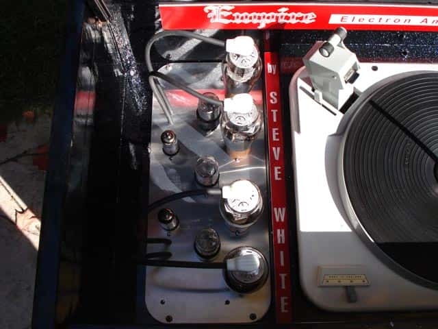
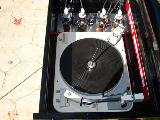
Here is a 1960’s style custom console stereo I built displaying the vacuum tube amplifier right next to the Garrard type A turntable. The 807 tube amplifier has a conservative output of 30 watts per channel and uses 6SN7 and 12AU7 pre amp tubes. The speakers are a pair of Jensen 15″ drivers and a pair of DeForest 3″ tweeters in each cabinet. The entire project took two months to build.

You can see more of Steve’s custom work on his Vacuum Tube Amp web site.

The Titan – Newest (and biggest) Vacuum Tube Amp from Steve

Just in from our friend Steve W. in Canada (who constructs the most amazing vacuum tube amplifiers)…

The best way to describe this next amplifier is it’s a Titan. It has to be the biggest, baddest, heaviest and most powerful amplifier I’ve made to date! Weighing in at just under 60 lbs. this push-pull-parallel EL-34 / 6L6 is conservatively rated at 110 watts per channel using EL-34 tubes. Capable of driving 4 or 8 ohm speakers via a switch on the back panel, this amp is a tube roller’s dream.

Simply by plugging in which rectifier tubes you want to use, be it a pair of 5Y3’s, 5R4’s, 5U4’s or even 5AR4’s you can match the correct plate voltage with what ever power tubes you choose, be it a set of 6V6’s, 6L6’s, 5881’s Kt-66’s, Kt-77’s, EL-34’s, or even 7591’s.

You also have the choice of running the amp in push-pull instead of push-pull-parallel simply by not installing the front four power tubes and switching off one of the two rectifier tubes via a switch located on the right hand side of the chassis. The signal and phase-inverter pre amp tubes used are my favourite large dual triodes 6SN7’s.

Now, about the transformers, seeing that this amplifier has to drive thirteen tubes, I thought it only made sense to use a separate filament power transformer. The transformer right next to the larger power transformer is the 20 amp filament transformer. By doing this, I’ve removed the heater load off of the main power transformer which now only has to supply the high voltages the amp needs.

Along with a hefty octet of 470 mfd 400 volt capacitors bought from West Florida Components, there is more than enough capacitance to keep this amp in the black during those high current moments when the music demands it.

By sharing the load this way, the main power transformer will not be taxed nearly as much. The output transformers are massive Hammonds that can easily handle the wattage this amp delivers.

You will notice a volume control knob located right smack in the middle of the mirror in front of the amp that’s surrounded in pure copper foil, and that is because this is a fully integrated power amp with a line stage pre amplifier built into it. That means you do not need to buy a separate pre amplifier. You only need to plug in your CD player, satellite, MP3, I-pod, or what ever type of line stage device you like to use, directly into the amplifier.

There are two benefits to an integrated amp, one, you don’t have to go out and spend money on a separate pre amp, and two, you are amplifying completely with tubes throughout the whole amplifying process from pre amp to power amp, and that makes it sound better, way better!

Once again – amazing job, Steve! Thanks for sharing this with our readers.

A Console Stereo: Steve’s Legacy Project

We continue to be amazed at the work that our friend and customer from Canada, Steve White, does.

Luckily for us, Steve graciously shares his talents by allowing us to post pictures of his recent projects.

Here’s what Steve said about his console stereo:

If I were to ever to have a legacy, this project would have to be it! Ever since I was 5 years old I’ve wanted a console stereo. 38 years later and I finally have one.

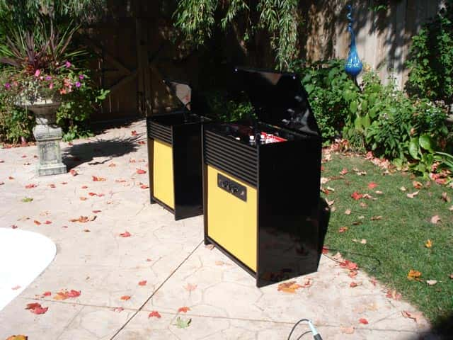
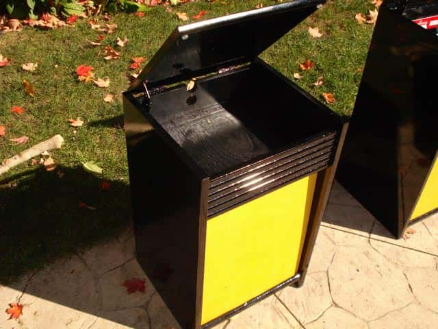
I took 2 old Magnavox cabinets that were originally the same size (both same as the large one) and added to the larger one to accommodate the turntable, and shrunk the other to be a satellite speaker to allow you place it where ever you wanted to in your room to give you the true stereo separation.

I then painted the cabinets Jet black with ice-pearl sparkles. I wanted the tube amplifier to be displayed unlike in older consoles, right next to the turntable, because to me the amp is art! I then completely restored this 1962 Garrard turntable that was reclaimed from an old console, and put the whole thing together.

Here is the result…. Sounds really nice too!

Job well done, Steve!

Opening Up and Tearing Down an IPOD Shuffle

Opening up and tearing down an IPOD Shuffle to see what’s inside…

The 3rd Generation of the IPOD Shuffle is a wonder of technology….1000 songs stored in an aluminum case smaller than a disposable lighter.

Did you ever wonder what electronic components make up the guts of an IPOD Shuffle?

You might be surprised at what goes into the circuitry of the IPOD Shuffle. In descending order by percentage of cost, the main components are:

logic, memory, metals, rechargeable materials, connectors, PCB, crystal, misc, capacitors, transistors, analog, diodes, magnetic, and plastics.

Here’s a partial breakdown by number of electronic components:

Capacitors – 65+
Resistors – 50+
Diodes – 4+

Pretty amazing what goes into equipment that measures only 45.2mm x 17.5mm x 7.8mm when fully assembled! This is possible because the components are extremely small surface mount components.

If you look at the cost breakdown by component family, it’s just as revealing. Naturally, the largest share is for memory in the form of IC’s. Over 70% (about $12.00 worth) is for logic and memory.

Early Crystal Radios

Requiring no battery, the crystal radio was one of the earliest forms of radio having been developed in the late 1800s and early 1900s. At this time the crystal radio sets were used to receive Morse code messages, but as time progressed the voice messages could also be received by such sets. This progression had much to do with an improvement in materials, which included the diodes and tuning coil. Even with an improvement in materials though, the construction of a radio set was fairly simple to achieve.

By the 1920s and 1930s radio was taking off, but the sets were expensive objects to buy and so the crystal radio was the cheap alternative that could be built at home. Most major newspapers would run guides on how to build such radios, and it was information that was put to good use during the Second World War. During the war, allied Prisoners of War made use of the materials that they had on hand, to build their own radios, to find out news of the fighting. The soldiers would use recovered wire for the tuning coil and antenna, and make diodes from everyday material, like the pencil lead.

The crystal radio is still used by many people around the world today, although now it is usually a hobby rather than a necessity. In most cases, radio sets are now fairly cheap and mass produced making the building of a crystal radio a pleasure rather than something that needs to be done.