Category Archives: Resistors

What are Current Sense Resistors and how do they work?

Efficiency has become the keyword in global trends in meeting demands for lower carbon-di-oxide emissions. Whether it is the smartening of the electrical supply grid or the electrification of our automobiles, the global trend is driving the need for electronic circuits to become more efficient. Knowing the level of current flowing through the circuit and reaching the load accurately is an important factor in gauging its efficiency for circuit designers and systems operators. This knowledge helps in maximizing operating performances of a battery, hot swapping server units, controlling motor speeds, and many more. Current sense resistors are inexpensive components that provide optimal solutions helping OEMs create more efficient circuit designs for a wide range of applications.

Current sense resistors are components helping to improve system efficiency by reducing losses. They have high measurement accuracy compared to other technologies, and they are ideally suited for helping developers measure currents precisely in automotive, industrial, and computer electronic designs.

Current sense resistors detect and convert current to voltage, using Ohm’s law. According to this law, the product of the current and the resistance value through which it is passing gives the voltage developed across the resistor. As these resistors feature very low resistance values, the voltage drops are equally insignificant, of the order of 10 to 150 mV in specific applications.

Design engineers place the current sense resistor in series with the electrical load, which causes the entire current to be measured to pass through it. As the voltage drop across the resistor is proportional to the current through it, measuring this drop provides an estimate of the load current. Measuring the voltage drop is usually accomplished through various amplifier options such as operational, differential, and instrumentation amplifiers. Selecting the right current sense resistor amplifier for a specific application involves looking at the input common-mode voltage specification. This is the average voltage present at the input terminals of the amplifier.

With the current sense resistor sitting in series with the load, they can directly measure the current. Contrast this with indirect current measurement techniques using coils. Here the voltage is induced across a coil and is proportion to the current. As a series resistor senses current directly, it dissipates power. Therefore, series resistors tend to have very low resistance values.

Current sense resistors also feature a very low temperature coefficient of resistance or TCR. This feature defines its low drift with varying ambient temperature and its long-term stability. These characteristics make temperature dependency of current measurement to be very low, while increasing the accuracy.

However, when using very low ohmic resistors of the surface mount type the resistance of the solder pad and the copper tracks of the printed circuit board can be uncertain and more than the resistance of the current sense resistance itself. This can lead to inaccuracies in the current measurement. In addition, the TCR of the tracks of the PCB can be much higher than that of the series resistor element.

Therefore, it is necessary to use current sense resistors implementing the 4-wire Kelvin principle, as these employ additional leads for measuring current more accurately.

What are Memristors?

What are Memristors and where are they used?

Professor Leon Chua developed the memristor theory in 1971. A scientist discovered the behavior of memristors when he was working in a lab at HP, trying to figure out crossbar switches. Memristors are also known as matrix switches, as they behave as a switch when connecting multiple inputs to several outputs. When Professor Chua looked at the assortment of resistors, capacitors, and inductors for the switching, he noticed a vital missing component, calling it the memory resistor or memristor. In 2006, Stanley Williams developed the practical model of a memristor.

One can consider the memristor as the fourth class of electrical component, after the familiar resistor, capacitor, and inductor. However, unlike the others, memristors exhibit their unique properties only at the nanoscale. Theoretically, memristors maintain a relationship between the time integrals of voltage across and current through two terminals of an element, as they are passive circuit elements.

The resistance of a memristor, or memristance, varies according to its function. It allows access to the history of the applied voltage via tiny read charges. The presence of hysteresis defines the material implementation of its memristive effects. This is its fundamental property, which looks more like a non-linear anomaly. Therefore, memristance is a simple charge dependent resistance, with a unit of Ohm. However, it has its own advantages.

The memristor technology offers lower heat generation as it utilizes less energy. Used in data centers, it offers greater resilience and reliability under interruptions of power. While not consuming any power when idle, memristors are compatible with CMOS interfaces. It is possible to store additional information as memristors allow higher densities to be achieved.

Physically, the memristor has two platinum electrodes across a resistive material, and its resistance depends on its polarity, magnitude, and length. The device retains its resistance even when the voltage is turned off, which makes it a non-volatile memory device. The resistive material can be titanium dioxide or silicon dioxide. As voltage is applied across the terminals, the oxygen atoms within the material disperse towards one of the electrodes. This activity stretches or contracts the material depending on the polarity of the applied voltage, thereby changing the resistance of the memristor.

Depending on their build, memristors are of two types—Iconic thin film and molecular memristors, and magnetic and spin based thermistors.

The material property of iconic thin film and molecular memristors rely more on different material properties of the thin film atomic lattices and application of charge makes these display hysteresis. Using these materials scientists make memristors of Titanium dioxide, ionic or polymers, resonant tunneling diodes, and manganite.

In contrast, magnetic and spin based memristors rely more on the property of the degree of electron spin. Therefore, these systems are aware of the polarization of electronic spin. There are two major types of such memristors—the spintronic memristors, and the spin torque transistor memristors.

With the practical demonstration of memristor manufacturing, their potential application has led to a rapid increase in research for using them in analog and digital circuits, such as programmable logic controllers, computers, and sensors. This has also led to development of theoretical models of memristors—Verilog-A, MATLAB, and Spice.

How Do You Read Resistor Values?

Resistors range from huge multi-watt giants to sub-miniature surface mount devices (SMDs) and parts with different types of leads in between. The larger varieties do not pose much of a problem as they usually have a big-enough surface for printing the value of the resistance, its tolerance, and other necessary specifications. For smaller sizes, codes are generally used for letting the user know the details of the resistor.

Two common methods are under use for identifying resistors – color coding for resistors with leads and number coding for SMD resistors. Color coding is an easy way to convey a lot of information concisely and effectively. One of the advantages is that specifications of the resistor are visible irrespective of its orientation on the PCB – very useful for overcrowded boards. As SMD resistors have only limited surfaces, number coding is more suitable.

Color coding for resistors

Resistors with color coding come with one of two standard codes – the 4-band code or the 5-band code. The 4-band coding is used more with resistors of low precision with 5, 10, and 20% tolerances. Higher precision resistors with tolerances of 1% and lower are marked with 5-band color codes.

The colors used have their own values. For example, Black represents zero, Brown represents one, Red represents two, Orange represents three, Yellow represents four, Green represents five, Blue represents six, Violet represents seven, Gray represents eight, White represents nine, Gold represents 0.1, and Silver represents 0.01.

For tolerances, Gray represents ±0.05%, Violet represents ±0.1%, Blue represents ±0.25%, Green represents ±0.5%, Brown represents ±1%, Red represents ±2%, Gold represents ±5%, Silver represents ±10%, while an absence of color represents ±20%.

The 4-Band color coding scheme

The 4-band color coding has thee color bands crowded on one side with the fourth band separated from the others. One has to read the code from the left to right beginning with the crowded colors on the left and the separated color band on the extreme right. Starting from the left, the first two color bands represent the most significant digits of the resistance value, while the third band represents the multiplier digit. The isolated fourth band is the tolerance band. As an example, a resistor of 4.7KΩ, 5% value will have the colors bands Yellow, Violet, and Red representing 4700Ω, with a fourth band of Golden color. In cases where there are only three color bands, it means the resistor has a ±20% tolerance.

The 5-band color coding scheme

High quality, high precision resistors with tolerances of 2%, 1% or lower are represented by five color bands, with the first three denoting the three most significant digits of the resistance value. The fourth band represents the multiplier value, while the fifth stripe gives the tolerance. Some resistors have an additional sixth band denoting the reliability or the temperature coefficient.

Number coding for SMD resistors

SMD resistors usually have three or four numbers on them, depending on whether they are of 5% or 1% tolerance. The last number is the multiplier with the others representing the most significant digits of the resistance value. In some cases, an alphabet is used, representing the resistor’s tolerance. However, if the alphabet is an R, it represents a decimal at its position. For more details, refer to this web site.

Do wirewound resistors suppress noise?

Specially designed wirewound resistors are used as noise suppressors in automotive ignition systems for reducing RFI or Radio Frequency Interference caused by electrical discharges. These resistors are usually placed in the leads and or caps of spark plugs and in the rotor of the distributor.

A gasoline engine generates high frequency electromagnetic Interference or EMI. This is commonly referred to as RFI or Radio Frequency Interference that comes primarily from the high-voltage side of the automotive circuit. At these places, the ignition system produces sparks at the coil that converts the battery voltage into high-voltage pulses. These pulses appear at the distributor, which routes the high voltage to the appropriate plug. Here, the spark ignites the air/fuel mixture in the combustion chamber producing the power that drives the crankshaft. Diesel engines do not have spark plugs as the air/fuel mixture is compressed to ignite and hence, diesel engines produce negligible EMI/RFI.

The high-voltage ignition pulses have a very rapid current change that generates an electromagnetic field around the ignition system. When electricity bounds through air, it passes through the air molecules, ionizing some of its atoms. As these atoms de-ionize, they release a tremendous amount of RFI. Although the frequencies are random and appear only for fractions of a second at a time, they affect almost any type of electronic device installed nearby to some degree.

Not only do these disturbances interfere with telephone and radio communications, they can even disrupt engine functioning and ABS control electronics. This type of interference sounds like a huge amount of crisps, crackles and rattles in radio receivers in communication systems.

International legislation requires manufacturers to reduce these disturbances to an acceptable level. That means the RFI must be reduced to a level so that there is no appreciable interference with the functioning of receivers not on the vehicle itself. Interference Suppression Regulations describe the RFI damping characteristics that manufacturers are required to follow, for example, VDE 0874 to 0879, CISPR or Council Directive 72/245/EEC, and usually differs from country to country.

Manufacturers usually track down the sources of RFI and limit it either at its source or filter it out before it can reach the instruments. The simplest and easiest method of prevention is by installing resistive spark plugs, resistive leads or ignition suppressor resistors. These contain internal impedance to dampen unnecessary emissions from the ignition system. Some manufacturers resort to redesigning the grounding circuit or installing feed-through/bypass capacitors.

Conventionally, spark plug leads usually carry a resistance of 6 to 15 Kohms per meter, and that makes them poor transmitters of RFI. However, electrical ignition systems may be sensitive to varying resistances in the spark-plug leads due to different lengths and can give mixed signals to the control module. Therefore, it is preferable to have solid-core wires with noise-suppressor resistors screwed onto brass fittings at the ends. This helps to maintain an equal resistance on each cylinder.

Use of noise suppressors is the best solution for reducing RFI. These resistors are designed for specific ignition systems and have the finest damping characteristics that do not cause disturbances to the ignition pulses. It usually suffices to place the resistors in the rotor of the distributor, in the spark plug caps or in the leads.

Learn about metal film resistors

Resistors are a common passive item in any electronic assembly. They are used for restricting the amount of current flowing in a circuit; acting much as a valve does in a water pipeline. The most commonly in use are carbon, thick metal and thin metal film resistors. The film forms the resistive material of the resistor.

The axial resistor is usually a cylindrical conductive film on a non-conductive ceramic carrier. Two leads projecting from both ends of the resistance help in connecting the item electrically within a circuit. Although the appearance of a metal film resistor is very similar to that of a carbon film resistor, the former has much better properties of stability, accuracy and reliability.

A cylindrical ceramic core of high purity forms the base of a metal film resistor. Manufacturers mostly use a method known as sputtered vacuum deposition to deposit a thin metal layer on this ceramic base. This combination is then kept at a low temperature for a long period, which results in very good accuracy for the resistor. Mostly, the resistance material used is nickel chromium (NiCr), however, for special applications, other alloys such as tin and antimony, tantalum nitride with platinum and gold are used as well.

The thickness of the metal film strongly governs the stability of the resistance. Typically, a metal thickness of 50-250nm is a good compromise between better stability and lower resistance value. For connecting to the circuit, two end caps with connecting leads are pressed on to the two ends of the resistor body.

To obtain the desired resistance a laser beam cuts a spiral slot in the thin metal layer. This is a more modern method as compared with grinding techniques and sandblasting used earlier for trimming the resistance value. Once the final value of the resistance is achieved, several layers of paint are placed on the resistor body, with each layer being baked individually.

Apart from providing a high dielectric strength, the coating protects against ingress of moisture and mechanical stresses. Color code bands on the body mark the resistor value along with the tolerance band. Metal film resistors are available with standard tolerances of 2, 1, 0.5. 0.25 and 0.1%, with the TCR or temperature coefficient of resistance lying between 50 and 100 ppm/K.

Metal film resistors demonstrate good properties for TCR, stability and tolerance. Because these resistors have a low voltage coefficient, they feature high linearity and low noise properties. Therefore, if any of your circuits need low noise, tight tolerance and low temperature coefficient properties, be sure to use metal film resistors. For example, active filters and bridge circuits use metal film resistors.

Metal film resistors show good reliability when operated from 80 percent down to 20 percent of their specified power rating. Although reliability generally increases if the resistor is derated 50 percent, going below 20 percent of the power rating at elevated humidity conditions usually diminishes reliability. Moreover, metal film resistors are more easily damaged by power overloads and voltage surges, as compared to carbon composition or wire-wound resistors.

Book for electronics beginners

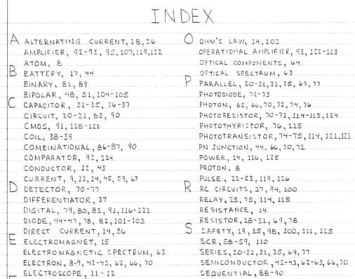
If you are new to electronics and want a good book to learn about circuits and electronic components, then I recommend that you check out this book:

Getting Started in Electronics by Forrest M Mims III

I’ve had my copy so long that it is almost time to replace it but even though it is an old, worn out copy, the information is still as good today as it was 15 years ago when I got my book. Of course, there are some things that won’t be found in here, but for the beginner, you can’t go wrong with this book.

The chapters are logically laid out and easy to read and each chapter builds on the previous lessons. I would recommend this book for anyone who wants to learn about electronics – from child to adult.

Introduction to electronics

Introduction to electronics

Android smartphone sales up a whopping 886%

Research firm, Canalys, reports that Android platform smartphone sales increased an amazing 886% in the 2nd quarter.

An even bigger accomplishment is the fact that Android based phones now account for 34% of the market – topping all other platforms including Apple’s popular iPhone platform.

The press release from Canalys also reports that Android devices combined reached almost 475,000 units in Q2 2010 from no presence in the country a year ago. The Google-backed Android is available in phones from HTC, Motorola, Samsung, Sony Ericsson and LG, among others.

In total, the US market for smartphones is the largest established market in the world, and it still continues to show rapid growth. In the 2nd quarter of 2010, there were 14.7 million smart phone units shipped.

More Allen Bradley carbon comp resistors now available!

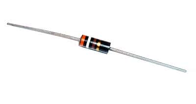
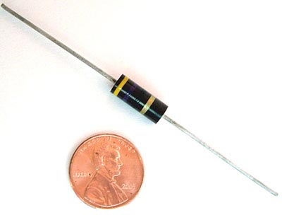
We’ve updated our resistor inventory and added many more NOS Allen Bradley carbon comp resistors. Between the 1W values and 2W values, we now have over 150 different 1W and 2W carbon comp resistors on hand!

Included in the selection are many Military (MIL-SPEC) Allen Bradley carbon comp resistors. The military resistors typically have a tighter tolerance than the standard resistors.

Allen Bradley carbon comp resistors are valued for their consistency and uniformity. The Allen Bradley corporation reference materials have this to say about their hot molded resistors:

Years of accumulated experience have shown that Allen Bradley hot molded resistors are unequaled for uniformity, predictable for performance, appearance, and freedom from catastrophic failure. Allen Bradley resistors are made by an exclusive hot molding process on automatic machines developed, built, and used only by Allen Bradley. There is such complete uniformity from one resistor to the next, million after million, and long term in-circuit performance can be predicted with usable accuracy. When used according to published ratings and recommendations, Allen Bradley hot molded fixed resistors will not open circuit nor exhibit erratic changes of resistance value. They are probably the most reliable of all electronic components.

We get frequent requests for other values so we were thrilled to get more for our stock! Quantities are limited – especially on the MIL-SPEC resistors.

Turn your old PC fans into mini wind generators

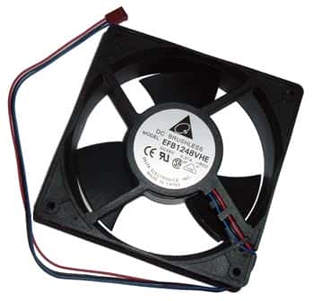
pc fanHere’s a great project that you can do either to experiment with wind turbines or to generate some energy! While the amount of energy produced is not overwhelming, this project can sure get your brain moving in the right direction.

The best thing about this project is that you probably already have everything you need lying around:

  • Thick plastic bottle
  • Old PC fan, bigger the better!
  • A few feet of small wire
  • A piece of wood about 1.5″ square and around 20cm long
  • Two lengths of steel tubing that slide inside of each other, about 1/2″
  • 6 Schottkey diodes
  • Epoxy
  • Super Glue
  • Zip ties
  • An old CD

You can find the full instructions including video here: http://www.instructables.com/id/Upcycle-your-old-PC-fans-into-mini-wind-generators/

If you want to have a kid-friendly wind turbine kit that already has all the pieces you need, we sell one of those. Our kits come with full instructions and all the materials needed to try your hand at creating a source of renewable energy – a wind turbine. The kit also comes with different experiments you can try with your wind turbine once it’s assembled. Great project for summer for the kids!

Application information for Allen Bradley resistors

Allen Bradley resistors are one of the best sellers on the West Florida Components web site with good reason.

The following information has been compiled to aid in the everyday selection and application of Allen-Bradley hot molded resistors. The statements should be helpful in evaluating the use of all types of AB hot molded resistors in broad general terms, and are not to be interpreted to be precise or exact.

A comprehensive list is made of the standard normal resistance values in their available tolerance categories, the rated continuous working voltages for all hot molded types, the part numbers, and color codes – all information provided for all values from 1 ohm to 100M ohm, taking into account the available range of values for each type (as of 1985).

Allen Bradley Resistors

Allen Bradley Resistors

1 – Low value resistors exhibit less change due to humidity, temperature and voltage than high value resistors.

2 – Resistance changes due to increase in moisture content are always positive.

3 – Resistance changes due to humidity are temporary, and, in the case of Allen Bradley resistors, are reversible.

4 – Change of resistance which has occurred due to humidity may be essentially eliminated by conditioning the resistor at 100°C or by dry storage.

5 – The effects of humidity may be minimized by operating the resistor with as little as 1/10 rated wattage load.

6 – Resistance change due to load life is permanent and usually ultimately negative.

7 – Resistance change due to load life can be minimized 1% – 2% in many thousands of hours by 50% derating period. The same result can be attained by limiting the maximum operation surface temperature of the resistor underload to 100°C. Permanent resistance changes as a result of storage of temperatures below 100°C are negligible, even for extended time periods.

8 – Resistance change due to soldering is positive and may be permanent if the resistor has excessive moisture present in its body. It can be greatly minimized if resistors are dry at the time of soldering.

9 – The temperature characteristics of Allen Bradley resistors is positive above +80 and below -10.

10 – The temperature characteristics of Allen Bradley resistors is negligible from -10°C to +80°C.

11 – The voltage characteristic (negative) and the temperature characteristic (positive) of Allen Bradley resistors tend to cancel one another in an Allen Bradley resistor in an average operating conditions, where both significant voltage and elevated temperature are present.

12- The heat sink to which a resistor is connected affects its rating. Resistors operated in multiple should be derated unless adequate heatsinks are provided.

13 – The quality and reliability of Allen Bradley resistors is the same for, and independent of, any resistance tolerances shown on the resistor.

14 – Years of accumulated experience have shown that Allen Bradley hot molded resistors are unequaled for uniformity, predictable for performance, appearance, and freedom from catastrophic failure. Allen Bradley resistors are made by an exclusive hot molding process on automatic machines developed, built, and used only by Allen Bradley. There is such complete uniformity from one resistor to the next, million after million, and long term in-circuit performance can be predicted with usable accuracy. When used according to published ratings and recommendations, Allen Bradley hot molded fixed resistors will not open circuit nor exhibit erratic changes of resistance value. They are probably the most reliable of all electronic components.

This information was taken in part from the Allen-Bradley corporation reference book dated 1985.